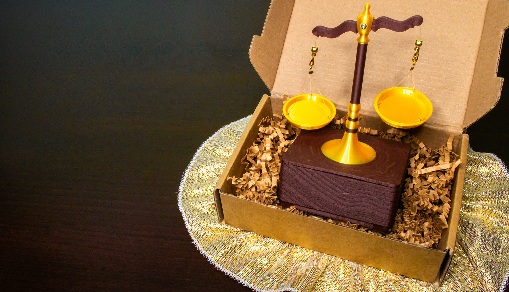
Project Overview
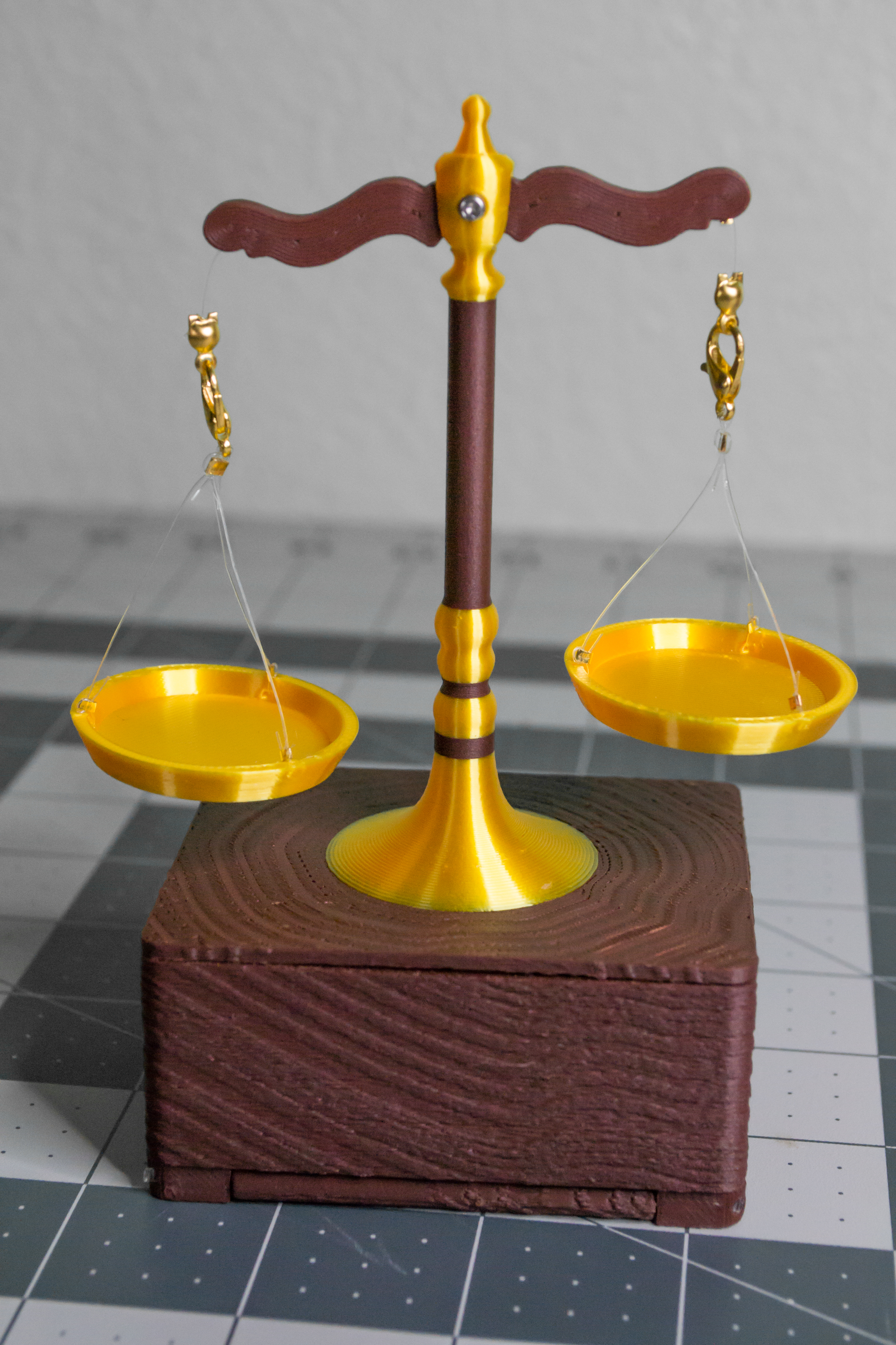
VintageScale is an electronic, USB- or battery-powered decorative mini scale that moves between two set positions using a servo and onboard analog controls. Designed to look like a vintage mechanical scale display, it adds life and character to any bookcase, shelf, or desk while adding a layer of hidden meaning based on what you choose to "weigh."
The motion is powered by my HexHands TwoPositionServo controller, a full-featured controller PCBA designed to drive a servo between two angles set with onboard potentiometers. The controller board can be powered by either USB Mini-B or three 1.2 V AAA rechargeable batteries through the installed battery contacts, and includes an easy plug-in servo connector along with other useful features.
VintageScale is just one of the many things you can do with a TwoPositionServo controller board. Whether you want to follow this guide step by step or use the board as a starting point for your own idea, I hope you have fun with this project and the controller board behind it.
For VintageScale, the two servo positions can represent two ideas, choices, or priorities. Whether that is Work Life, Logic Creativity, or something else, VintageScale can add meaning and character to your surroundings through a simple back-and-forth motion.
No programming is required for this build. The servo timing and two end positions are adjusted using the onboard potentiometers, and the battery-powered design makes VintageScale easy to place on a shelf, desk, bookcase, or anywhere else you want it displayed.
In this guide, I will show the electronics, servo setup, 3D printing, soldering, mechanical assembly, and controller settings used to build VintageScale.
Parts, Materials, and Tools
Here are all the components you will need to create this project. I have split the list into smaller groups so it is easier to check what you need before starting.
Filament and Power
| Image | Item | Qty | Source | Notes |
| - | - | - | - | - |
|  | Bambu Lab PLA Wood Rosewood | 1 spool | https://store.bambulab.com/products/pla-wood?id=43075831988360 | Used for the main wood-colored printed parts. Other wood or brown PLA can work, but fit and texture may vary. |
|
| Bambu Lab PLA Wood Rosewood | 1 spool | https://store.bambulab.com/products/pla-wood?id=43075831988360 | Used for the main wood-colored printed parts. Other wood or brown PLA can work, but fit and texture may vary. |
|  | Bambu Lab PLA Silk+ Gold | 1 spool | https://store.bambulab.com/products/pla-silk-upgrade?id=43128679792776 | Used for the text, scale details, and plate parts. Other gold PLA can work for a similar look. |
|
| Bambu Lab PLA Silk+ Gold | 1 spool | https://store.bambulab.com/products/pla-silk-upgrade?id=43128679792776 | Used for the text, scale details, and plate parts. Other gold PLA can work for a similar look. |
|  | Transparent PETG | Small amount | https://store.bambulab.com/products/petg-translucent?id=42235108098184 | Used for the transparent status-light window. White filament can also work if you do not have transparent PETG. |
| | 1.2 V AAA rechargeable batteries | 3 | Any reliable brand | Battery power option for the controller board. |
| | USB Mini-B cable | 1 | Any reliable brand | USB power option for testing or display use. |
| Transparent PETG | Small amount | https://store.bambulab.com/products/petg-translucent?id=42235108098184 | Used for the transparent status-light window. White filament can also work if you do not have transparent PETG. |
| | 1.2 V AAA rechargeable batteries | 3 | Any reliable brand | Battery power option for the controller board. |
| | USB Mini-B cable | 1 | Any reliable brand | USB power option for testing or display use. |
Electronics
| Image | Item | Qty | Source | Notes |
| - | - | - | - | - |
| 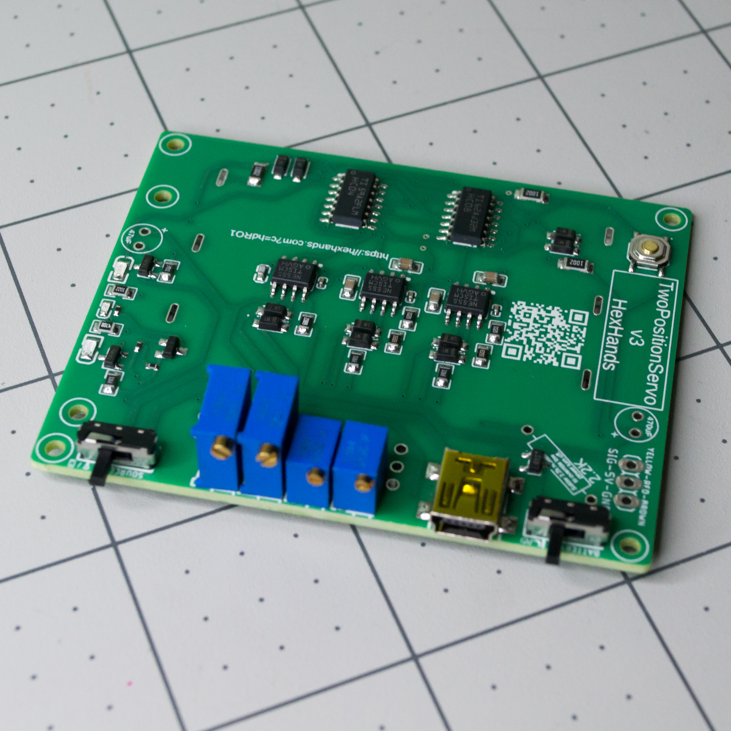 | HexHands TwoPositionServo controller PCBA | 1 | https://www.pcbway.com/project/shareproject/VintageScale_TwoPositionServo_9a4d9c96.html | Custom controller board for VintageScale control electronics. |
|
| HexHands TwoPositionServo controller PCBA | 1 | https://www.pcbway.com/project/shareproject/VintageScale_TwoPositionServo_9a4d9c96.html | Custom controller board for VintageScale control electronics. |
| 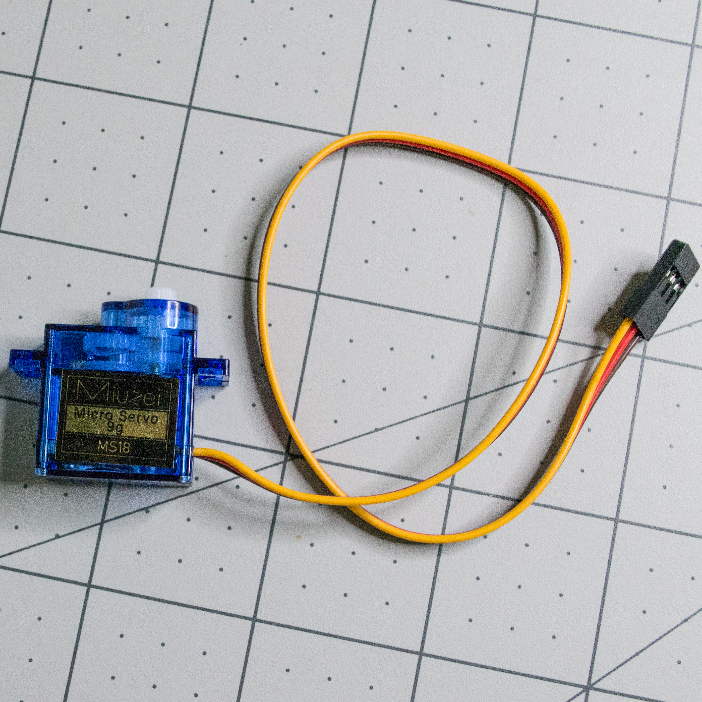 | Miuzei MS18 9 g micro servo | 1 | https://www.amazon.com/dp/B0FJQZSFMS | Three-wire servo for VintageScale motion control. |
|
| Miuzei MS18 9 g micro servo | 1 | https://www.amazon.com/dp/B0FJQZSFMS | Three-wire servo for VintageScale motion control. |
| 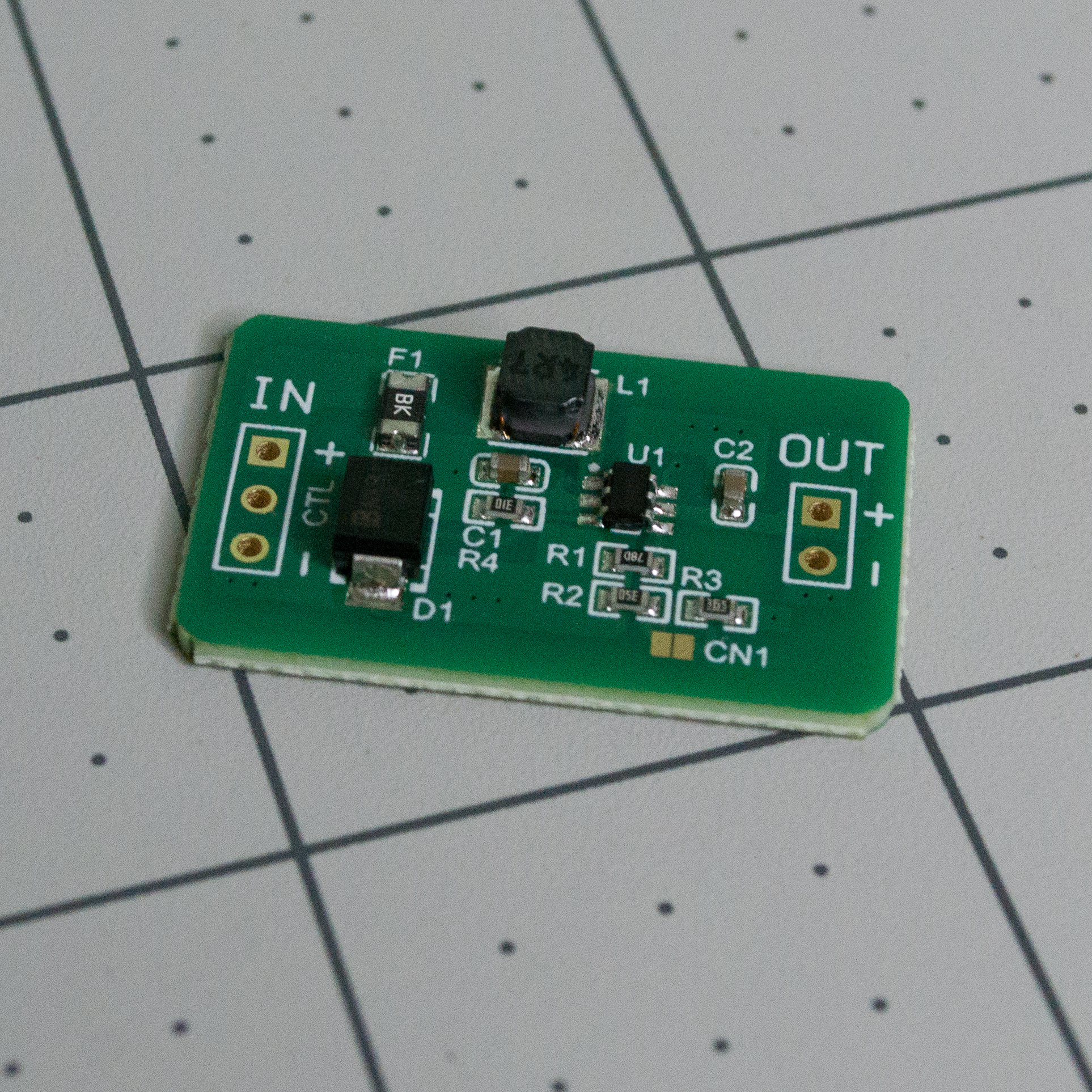 | QEBIDUM DC-DC converter | 1 | https://www.amazon.com/dp/B0B9T35QSZ | Boost converter for the battery-powered mode. |
|
| QEBIDUM DC-DC converter | 1 | https://www.amazon.com/dp/B0B9T35QSZ | Boost converter for the battery-powered mode. |
| 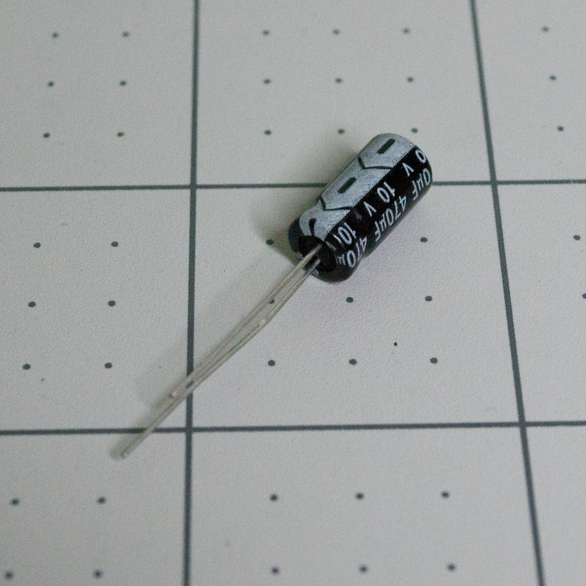 | 470 uF, 10 V electrolytic capacitor | 1 | https://www.amazon.com/dp/B01MSQOX0Q | Capacitor for the VintageScale circuit. Install with correct polarity. |
|
| 470 uF, 10 V electrolytic capacitor | 1 | https://www.amazon.com/dp/B01MSQOX0Q | Capacitor for the VintageScale circuit. Install with correct polarity. |
| 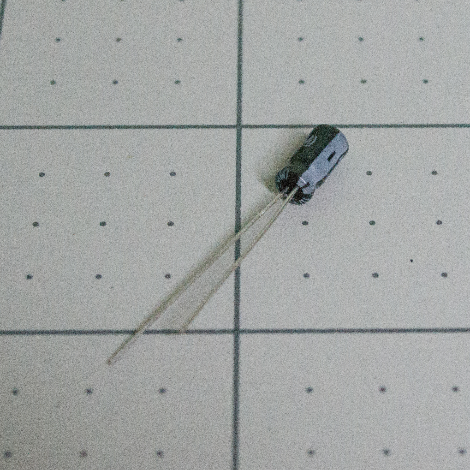 | 47 uF, 10 V electrolytic capacitor | 1 | https://www.amazon.com/dp/B01MSQOX0Q | Capacitor for the VintageScale circuit. Higher precision will work better if used for timing. |
|
| 47 uF, 10 V electrolytic capacitor | 1 | https://www.amazon.com/dp/B01MSQOX0Q | Capacitor for the VintageScale circuit. Higher precision will work better if used for timing. |
| 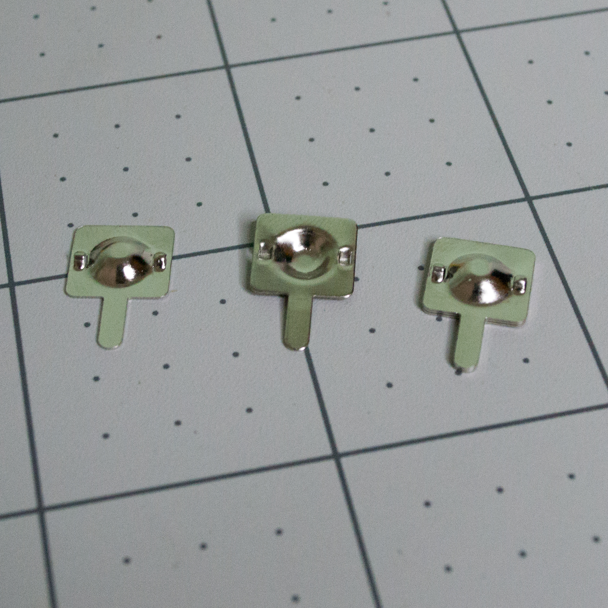 | Metal dome battery contacts | 3 | https://www.amazon.com/dp/B0B1ZJ8PNH | Positive battery contacts. |
|
| Metal dome battery contacts | 3 | https://www.amazon.com/dp/B0B1ZJ8PNH | Positive battery contacts. |
| 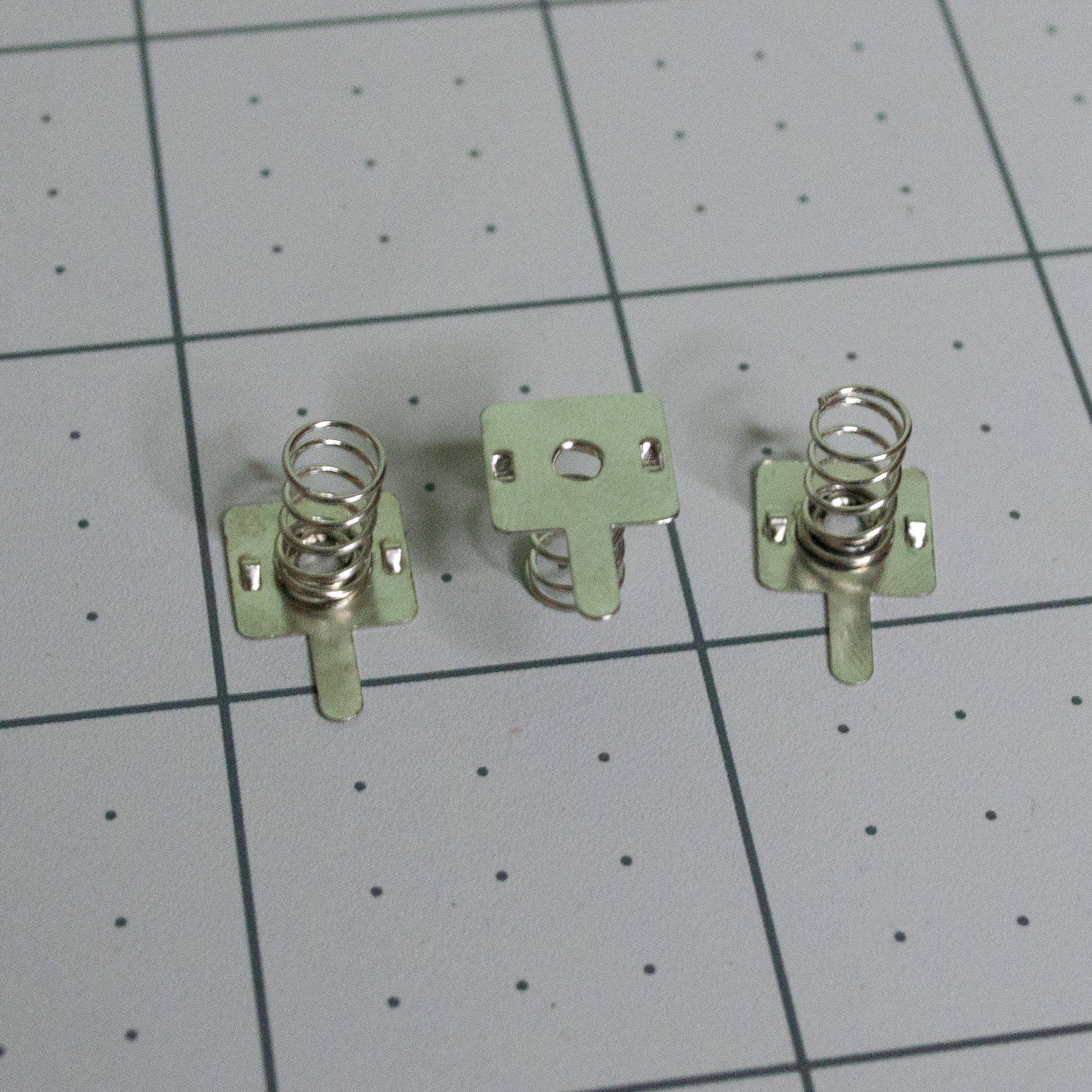 | Metal spring battery contacts | 3 | https://www.amazon.com/dp/B0B1ZJ8PNH | Negative battery contacts. |
|
| Metal spring battery contacts | 3 | https://www.amazon.com/dp/B0B1ZJ8PNH | Negative battery contacts. |
| 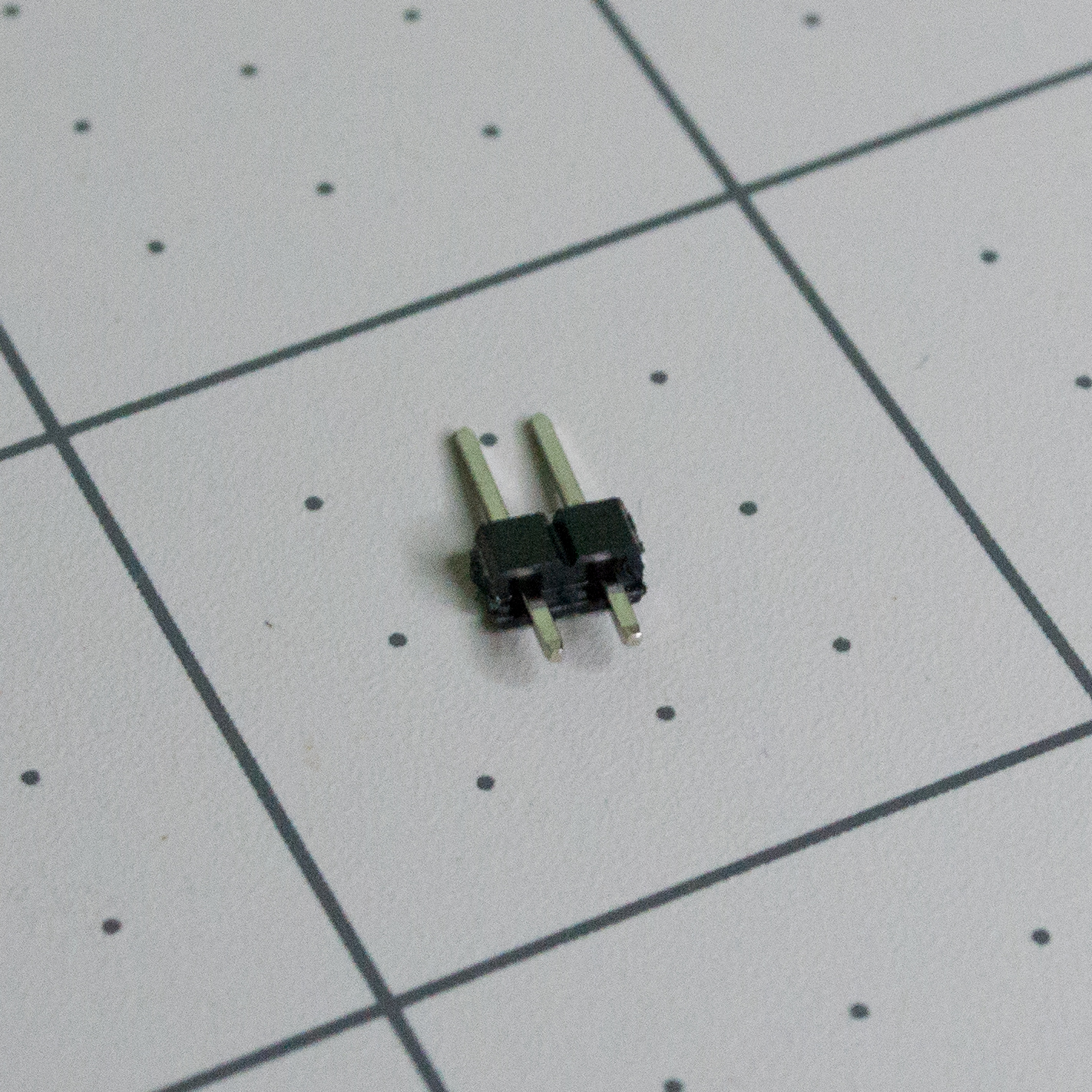 | 2-pin male header | 1 | https://www.amazon.com/dp/B06ZZN8L9S | Used with the DC-DC converter board. |
|
| 2-pin male header | 1 | https://www.amazon.com/dp/B06ZZN8L9S | Used with the DC-DC converter board. |
| 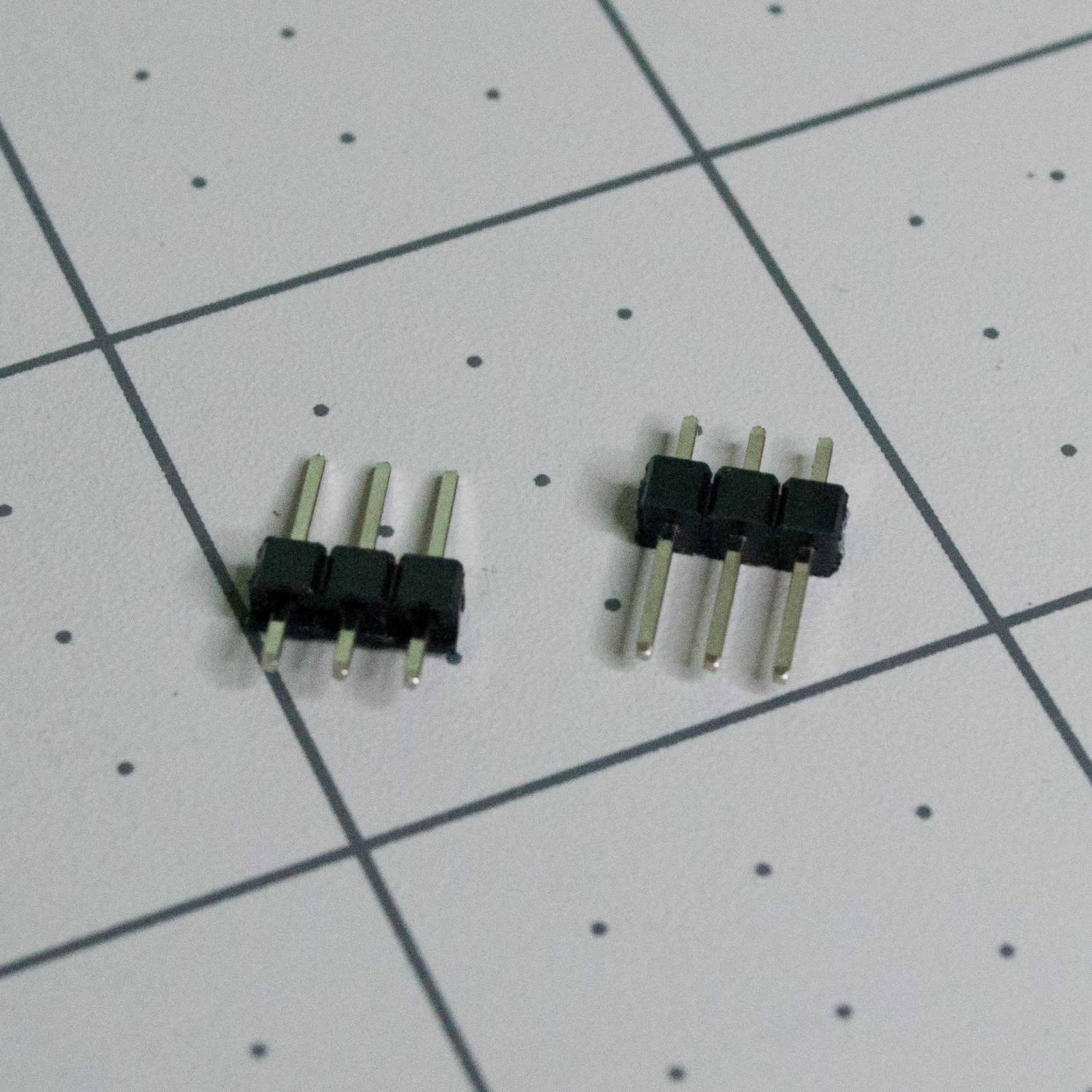 | 3-pin male headers | 2 | https://www.amazon.com/dp/B06ZZN8L9S | One header is for the servo connector; one is for the converter board. |
Hardware and Linkage Parts
| Image | Item | Qty | Source | Notes |
| - | - | - | - | - |
| 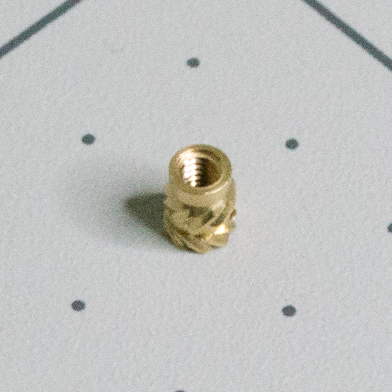 | Brass heat-set threaded insert | 1 | https://www.amazon.com/dp/B0DK16VY81 | Threaded insert for the M2, 8 mm battery-lid screw. |
|
| Brass heat-set threaded insert | 1 | https://www.amazon.com/dp/B0DK16VY81 | Threaded insert for the M2, 8 mm battery-lid screw. |
| 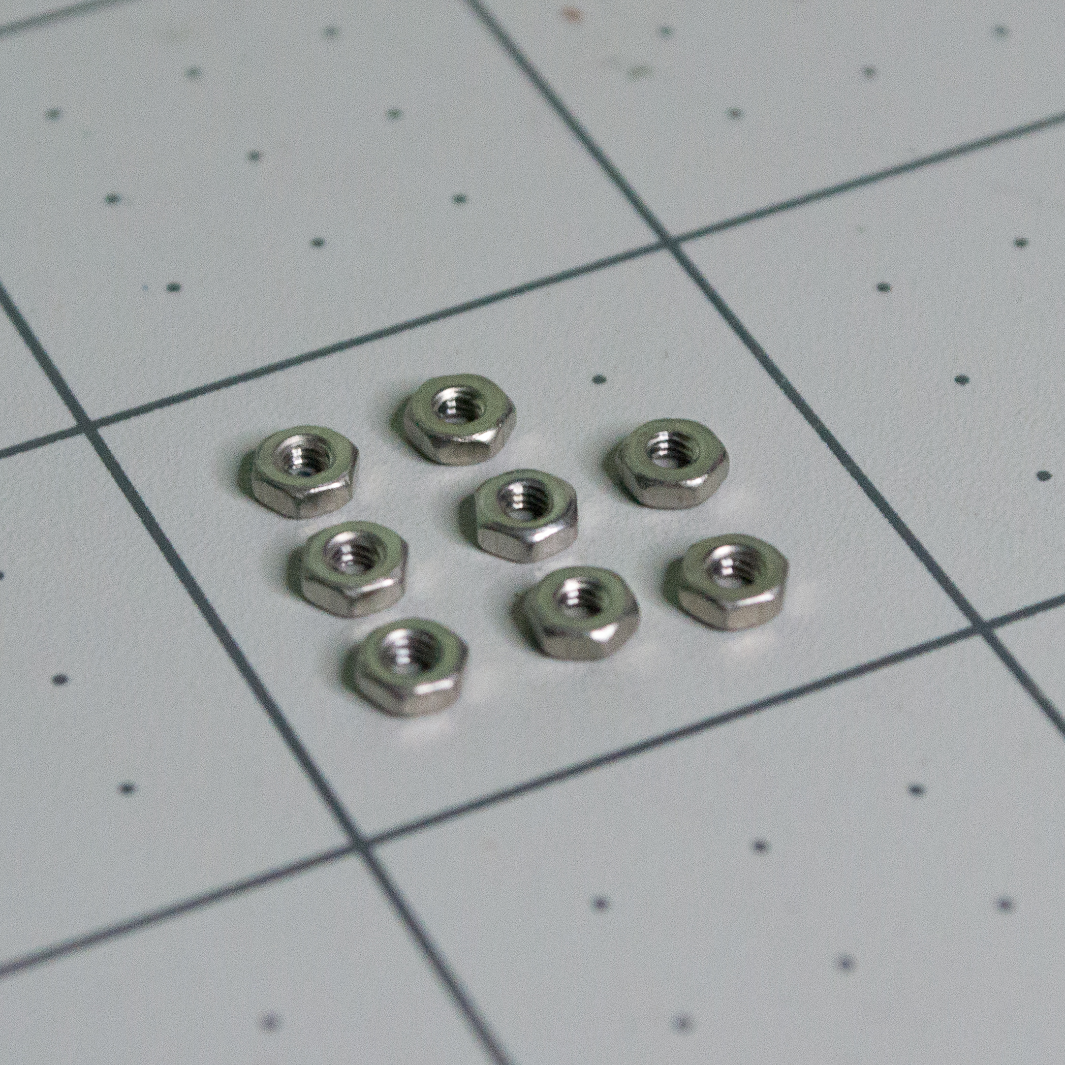 | M2 hex nuts | 8 | https://www.amazon.com/dp/B0CTJY6G5K | Four for the body/PCBA stack, two for the servo, and two for the fulcrum. |
|
| M2 hex nuts | 8 | https://www.amazon.com/dp/B0CTJY6G5K | Four for the body/PCBA stack, two for the servo, and two for the fulcrum. |
| 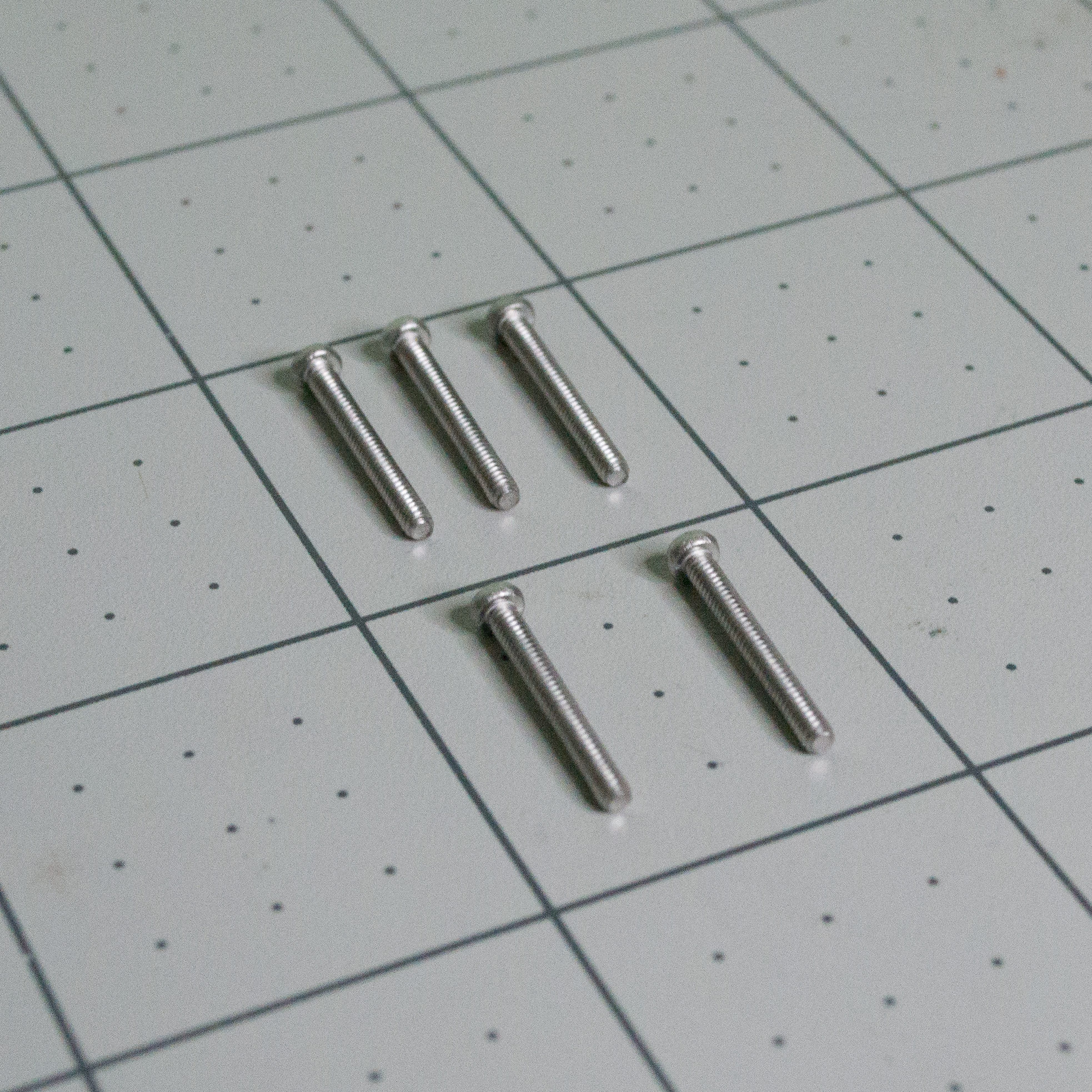 | M2, 16 mm machine screws | 5 | https://www.amazon.com/dp/B0CMCS9GRZ | Four for the body/PCBA stack and one for the fulcrum. |
|
| M2, 16 mm machine screws | 5 | https://www.amazon.com/dp/B0CMCS9GRZ | Four for the body/PCBA stack and one for the fulcrum. |
| 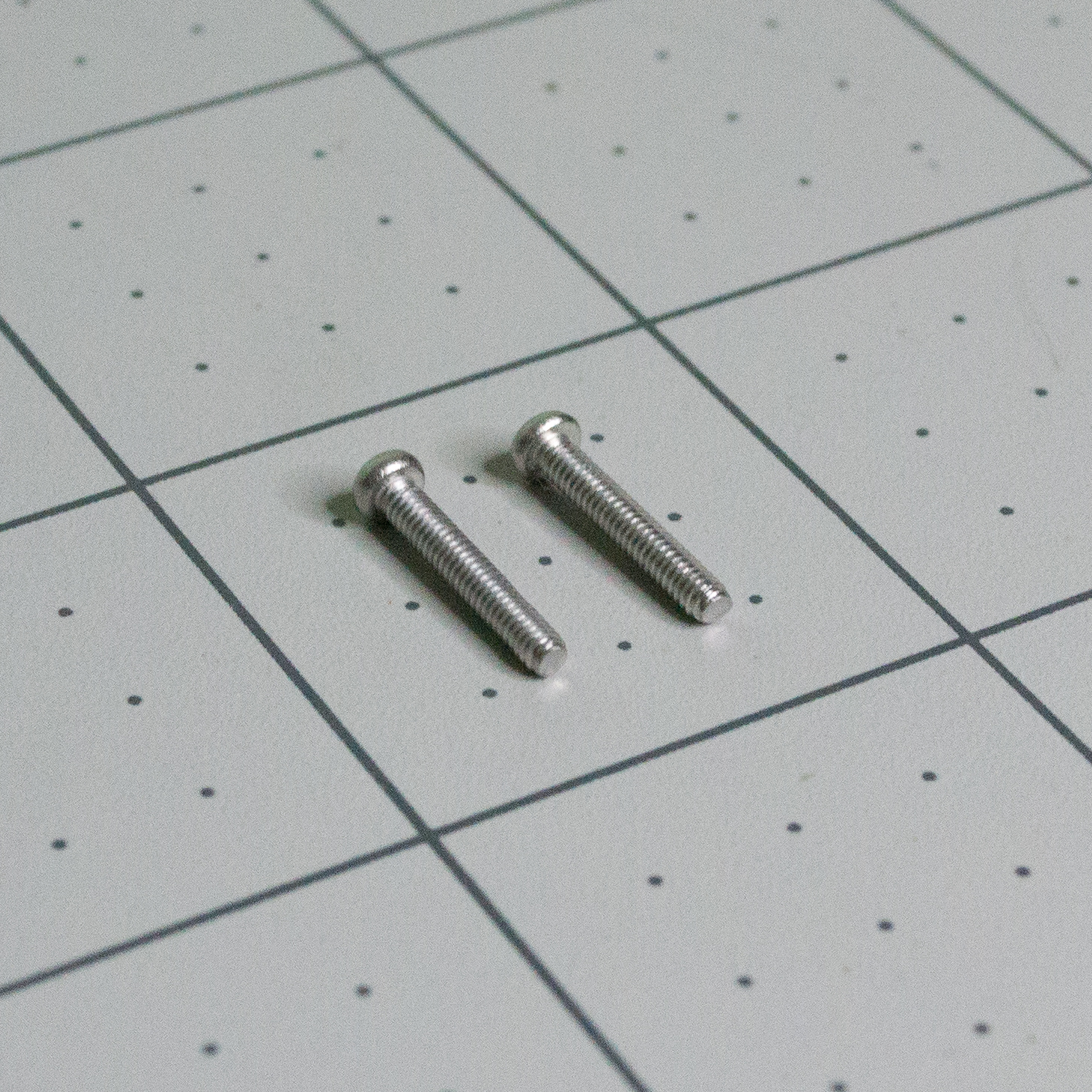 | M2, 12 mm machine screws | 2 | https://www.amazon.com/dp/B0CMCRCVY7 | Used to mount the servo. |
|
| M2, 12 mm machine screws | 2 | https://www.amazon.com/dp/B0CMCRCVY7 | Used to mount the servo. |
| 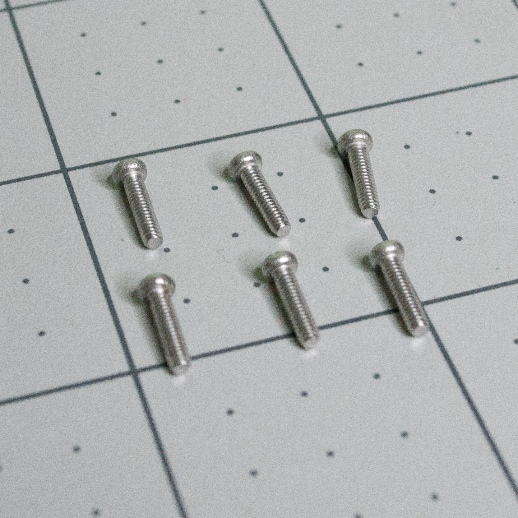 | M2, 8 mm machine screws | 6 | https://www.amazon.com/dp/B0CMCRW6N5 | One for the battery lid, four for the top/body, and one for the back. |
|
| M2, 8 mm machine screws | 6 | https://www.amazon.com/dp/B0CMCRW6N5 | One for the battery lid, four for the top/body, and one for the back. |
| 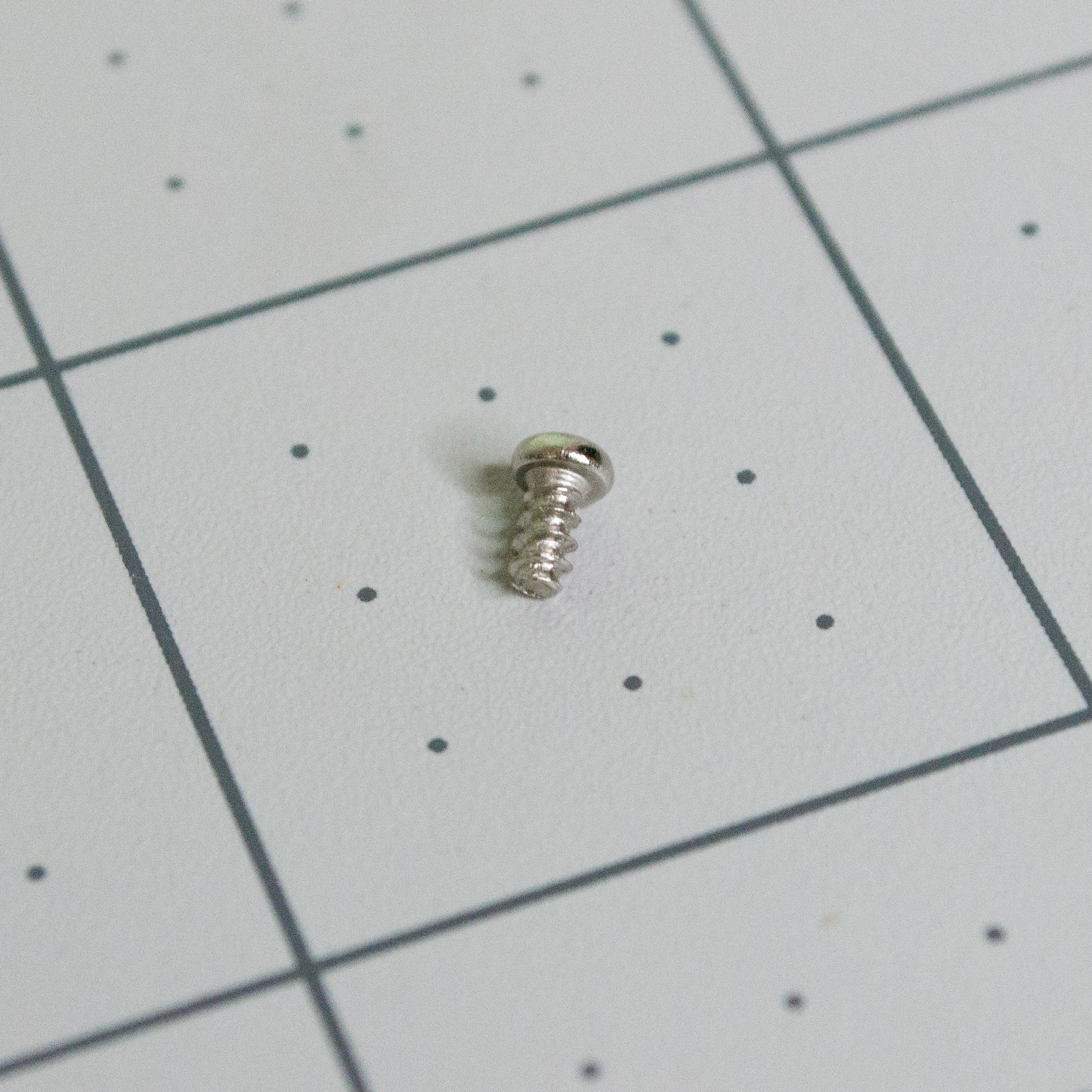 | Servo horn screw | 1 | https://www.amazon.com/dp/B0FJQZSFMS | Holds the printed Arm onto the servo output shaft. |
|
| Servo horn screw | 1 | https://www.amazon.com/dp/B0FJQZSFMS | Holds the printed Arm onto the servo output shaft. |
|  | Clear monofilament line | As needed | https://www.amazon.com/dp/B01FYGWZA2 | Used for the lever linkage and hanging scale plates. |
|
| Clear monofilament line | As needed | https://www.amazon.com/dp/B01FYGWZA2 | Used for the lever linkage and hanging scale plates. |
| 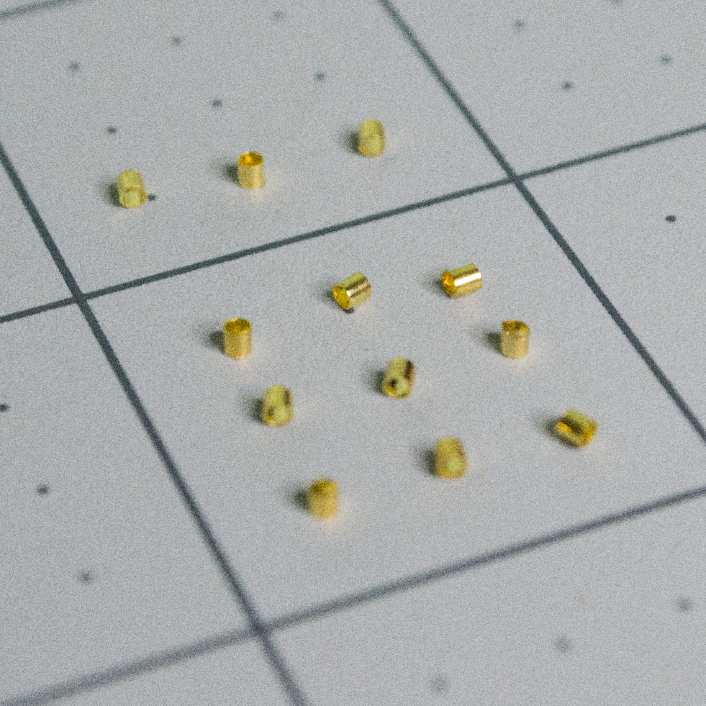 | Small gold crimp beads | 12 | https://www.amazon.com/dp/B0C7C61D19 | Used to lock the monofilament loops. |
|
| Small gold crimp beads | 12 | https://www.amazon.com/dp/B0C7C61D19 | Used to lock the monofilament loops. |
| 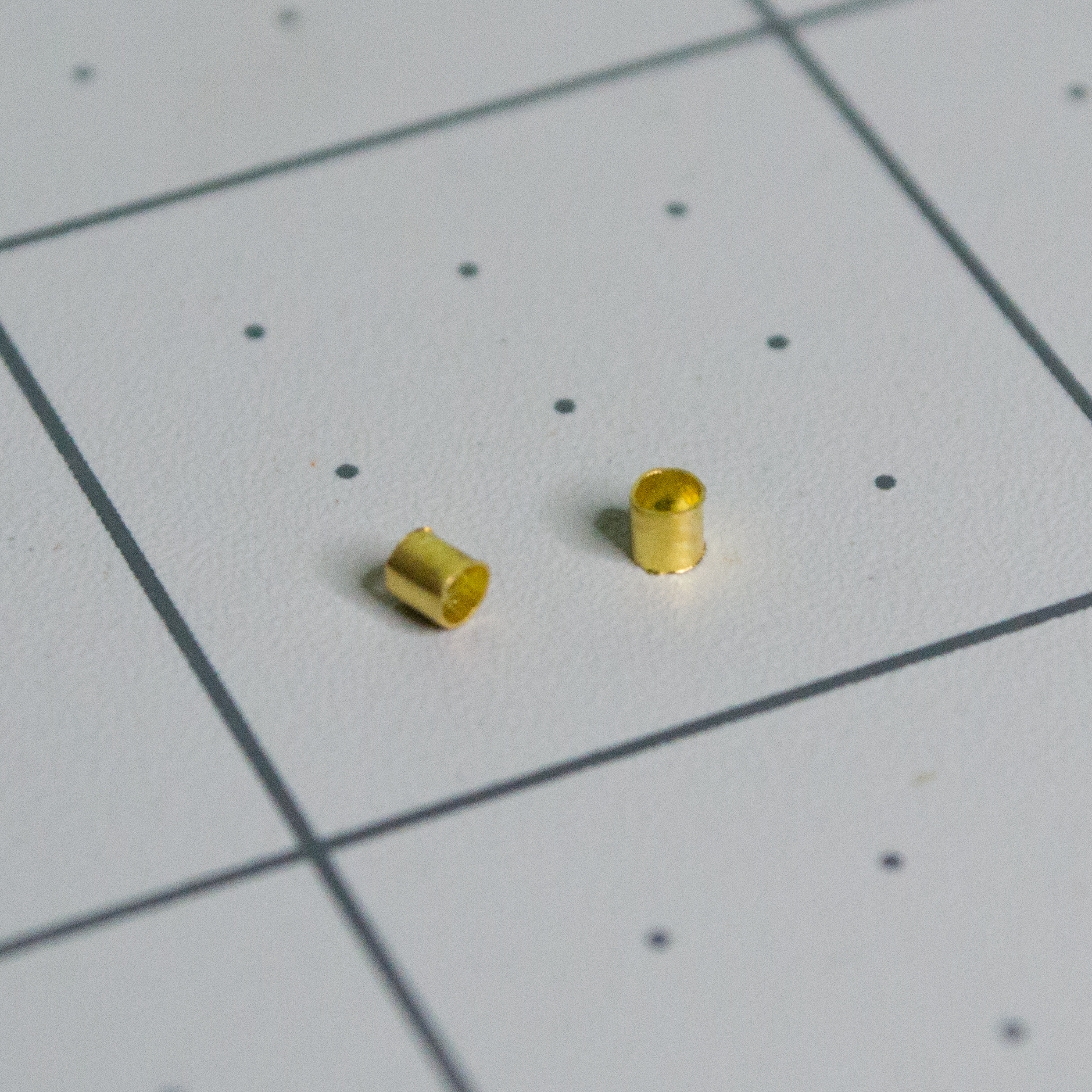 | Medium gold crimp beads | 2 | https://www.amazon.com/dp/B0C7C61D19 | One for each hanging plate assembly. |
|
| Medium gold crimp beads | 2 | https://www.amazon.com/dp/B0C7C61D19 | One for each hanging plate assembly. |
| 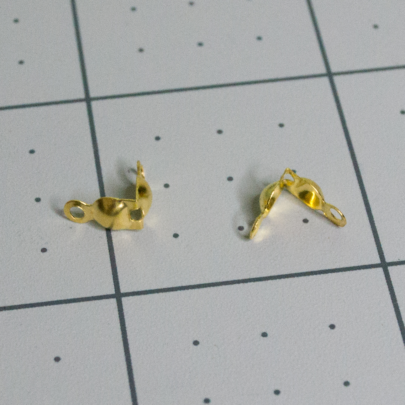 | Folded clamshell bead tips | 2 | https://www.amazon.com/dp/B0C7C61D19 | Decorative covers for the lever lines. |
|
| Folded clamshell bead tips | 2 | https://www.amazon.com/dp/B0C7C61D19 | Decorative covers for the lever lines. |
| 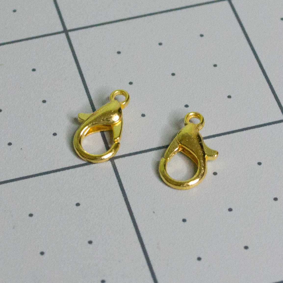 | Gold lobster claw clasps | 2 | https://www.amazon.com/dp/B0C7C61D19 | Used to hang the plates from the Lever. |
Printed Parts
The parts below are created in the 3D printing section. They are listed here so the full assembly checklist is in one place.
| Image | Item | Qty | Source | Notes |
| - | - | - | - | - |
| 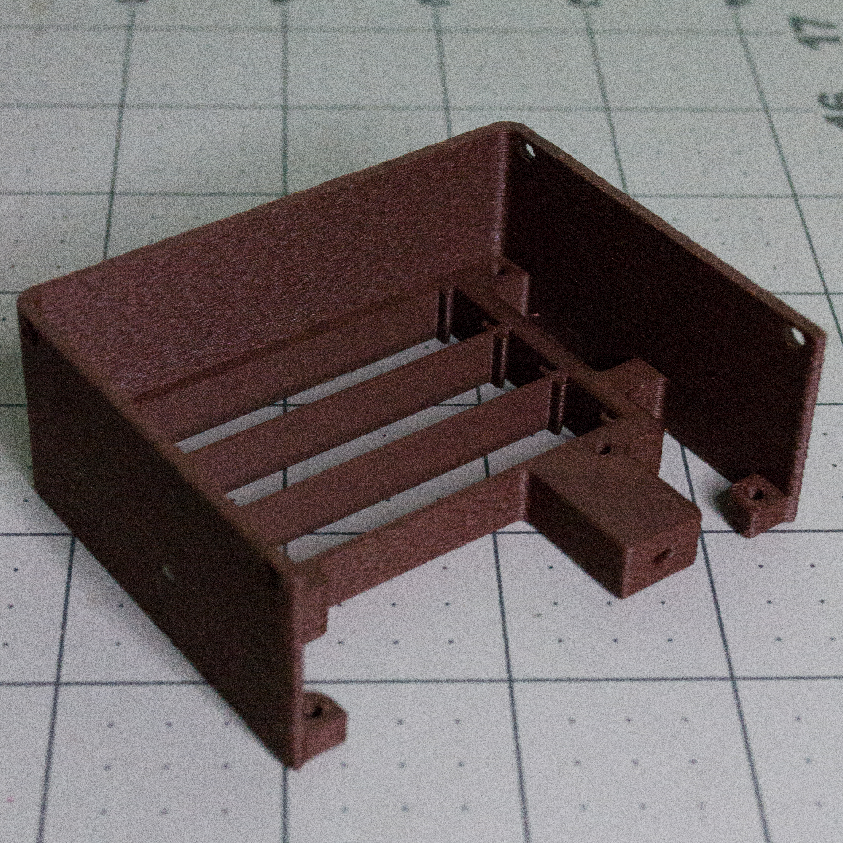 | Printed Body | 1 | 3D printed from project files | Main body shell with battery spaces and screw holes. |
|
| Printed Body | 1 | 3D printed from project files | Main body shell with battery spaces and screw holes. |
| 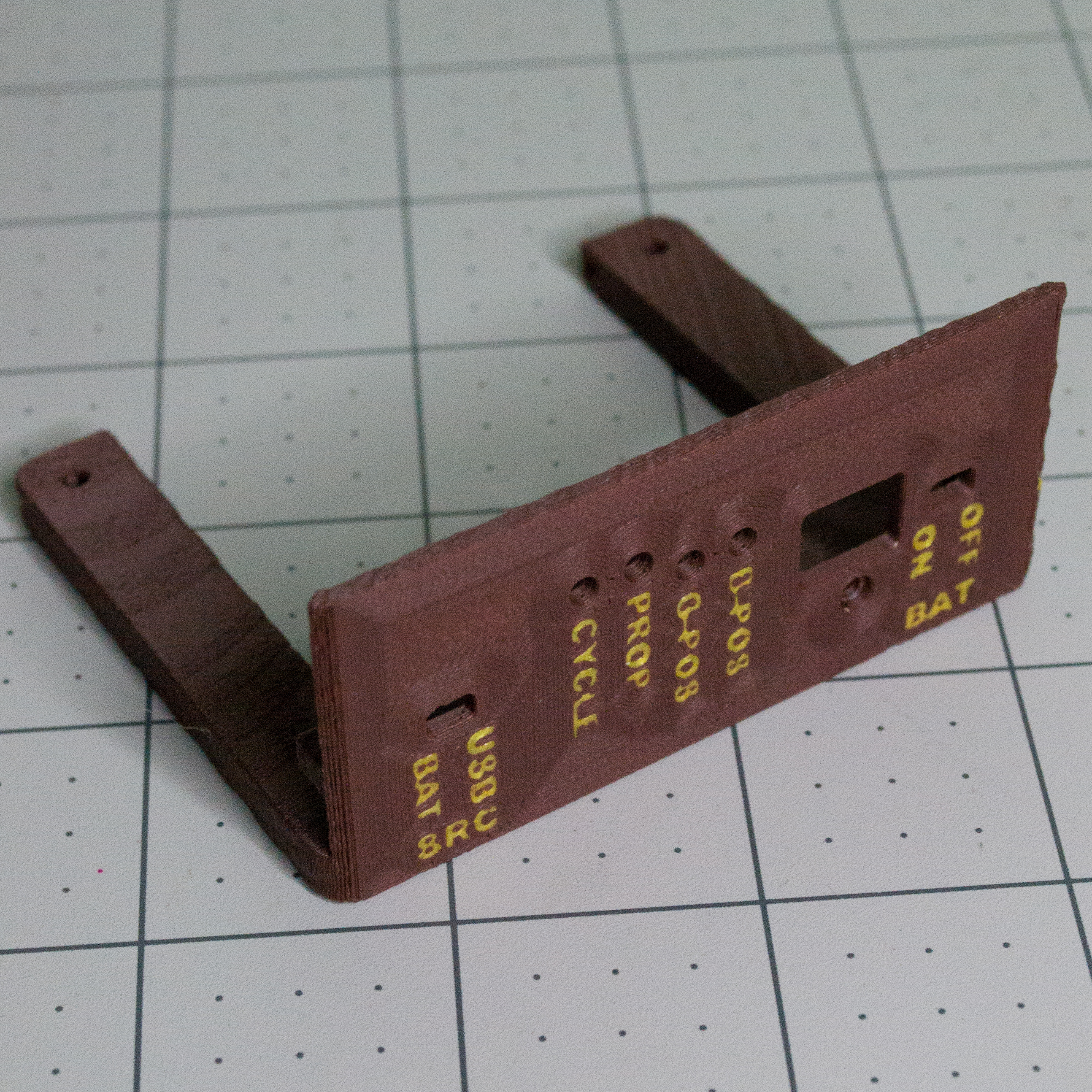 | Printed Bottom | 1 | 3D printed from project files | Slides into the Body and supports the PCBA. |
|
| Printed Bottom | 1 | 3D printed from project files | Slides into the Body and supports the PCBA. |
| 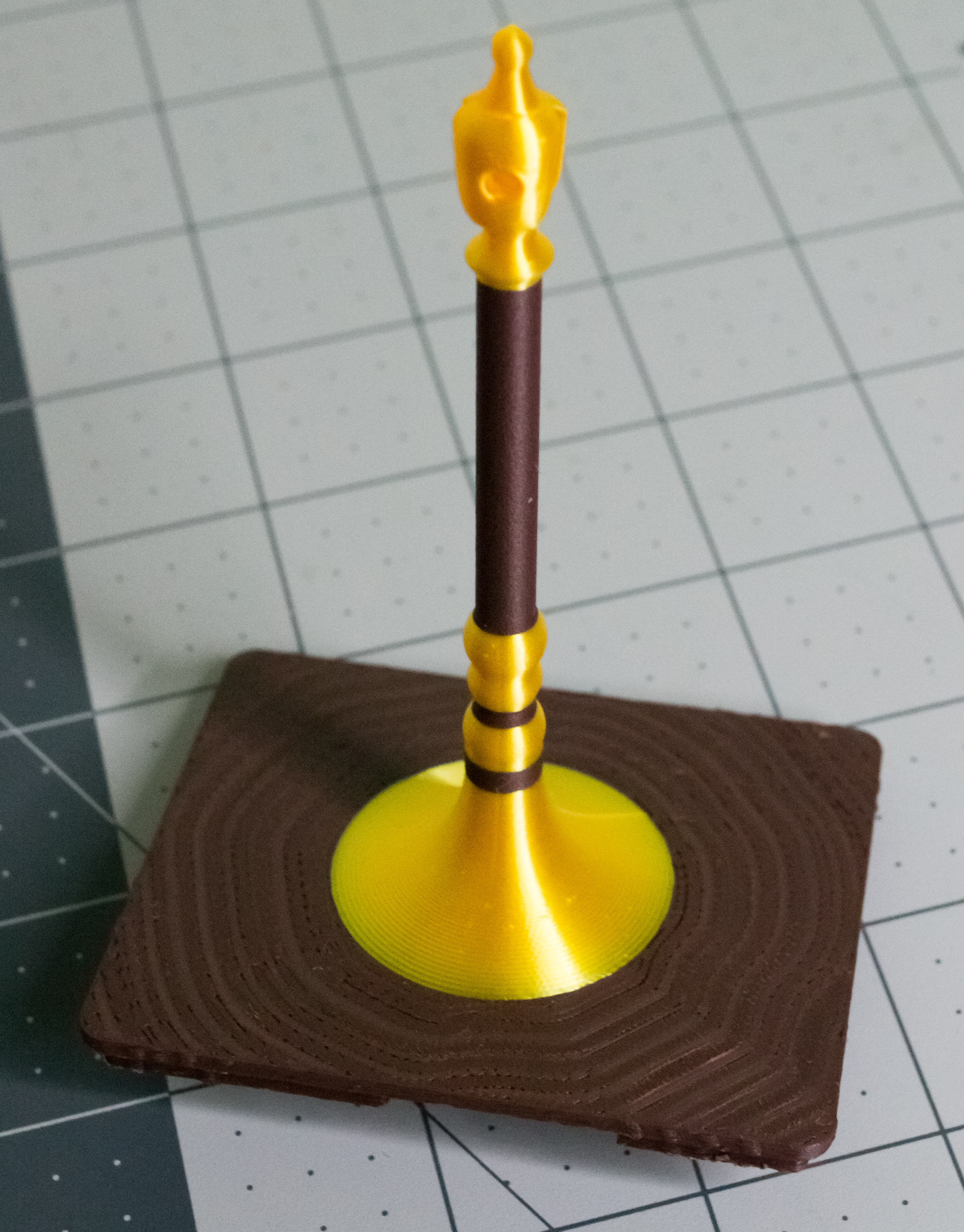 | Printed Top/Scale | 1 | 3D printed from project files | Top/scale structure with the servo mount and scale mast. |
|
| Printed Top/Scale | 1 | 3D printed from project files | Top/scale structure with the servo mount and scale mast. |
| 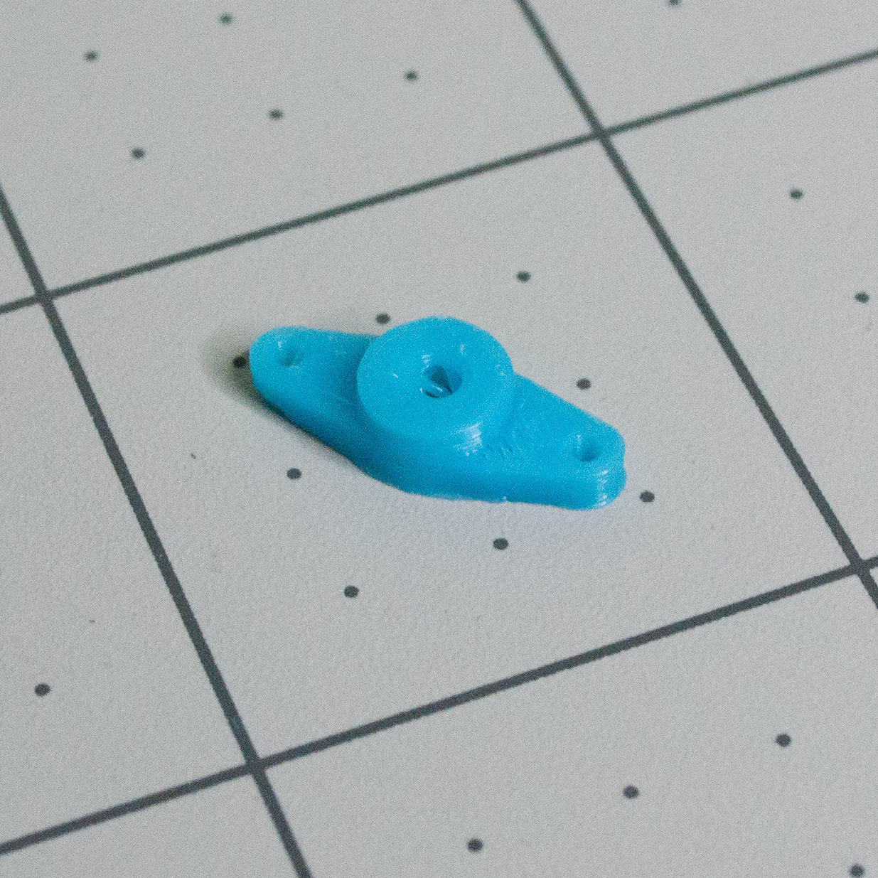 | Printed Arm | 1 | 3D printed from project files | Presses onto the servo output shaft. |
|
| Printed Arm | 1 | 3D printed from project files | Presses onto the servo output shaft. |
| 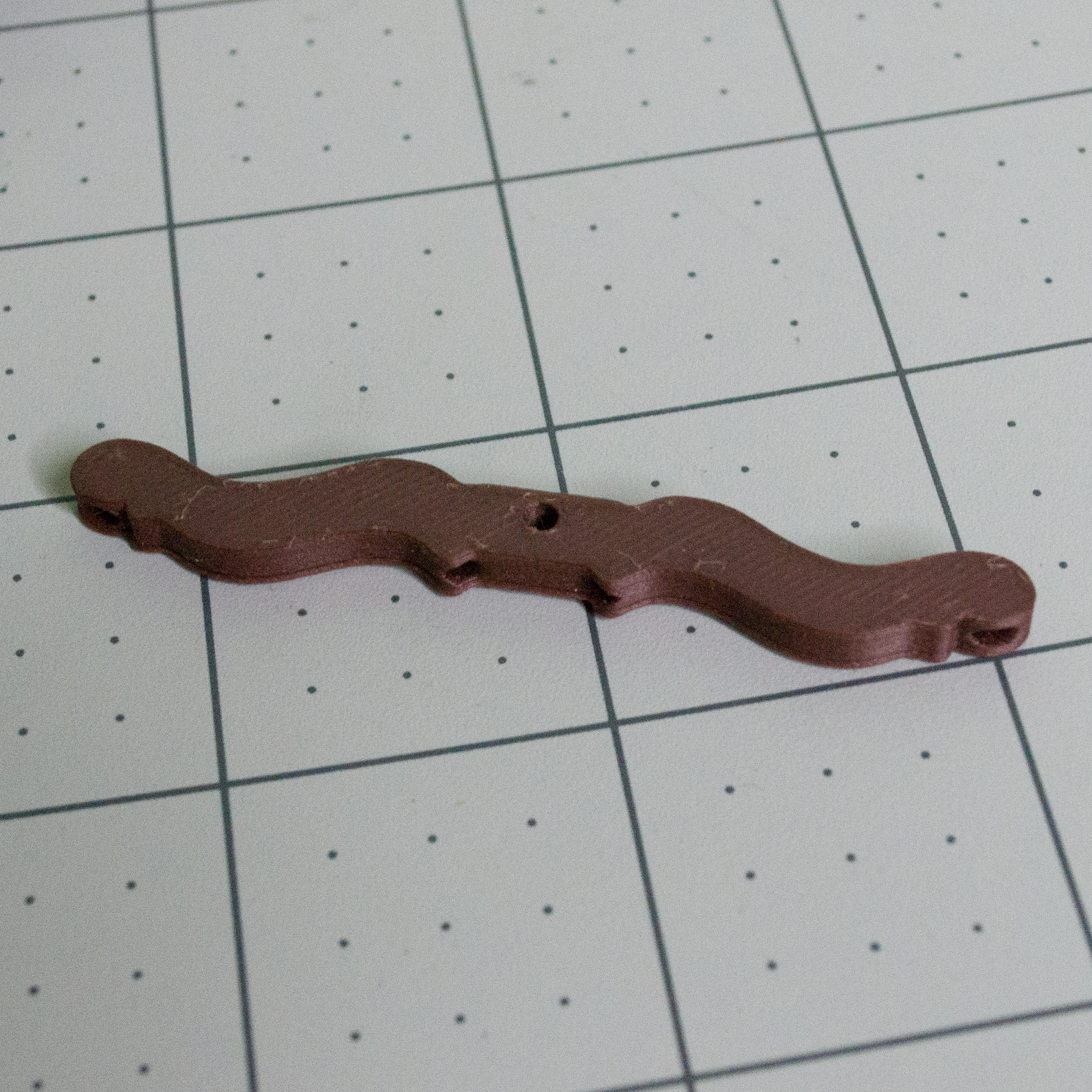 | Printed Lever | 1 | 3D printed from project files | Moves from the monofilament linkage. |
|
| Printed Lever | 1 | 3D printed from project files | Moves from the monofilament linkage. |
| 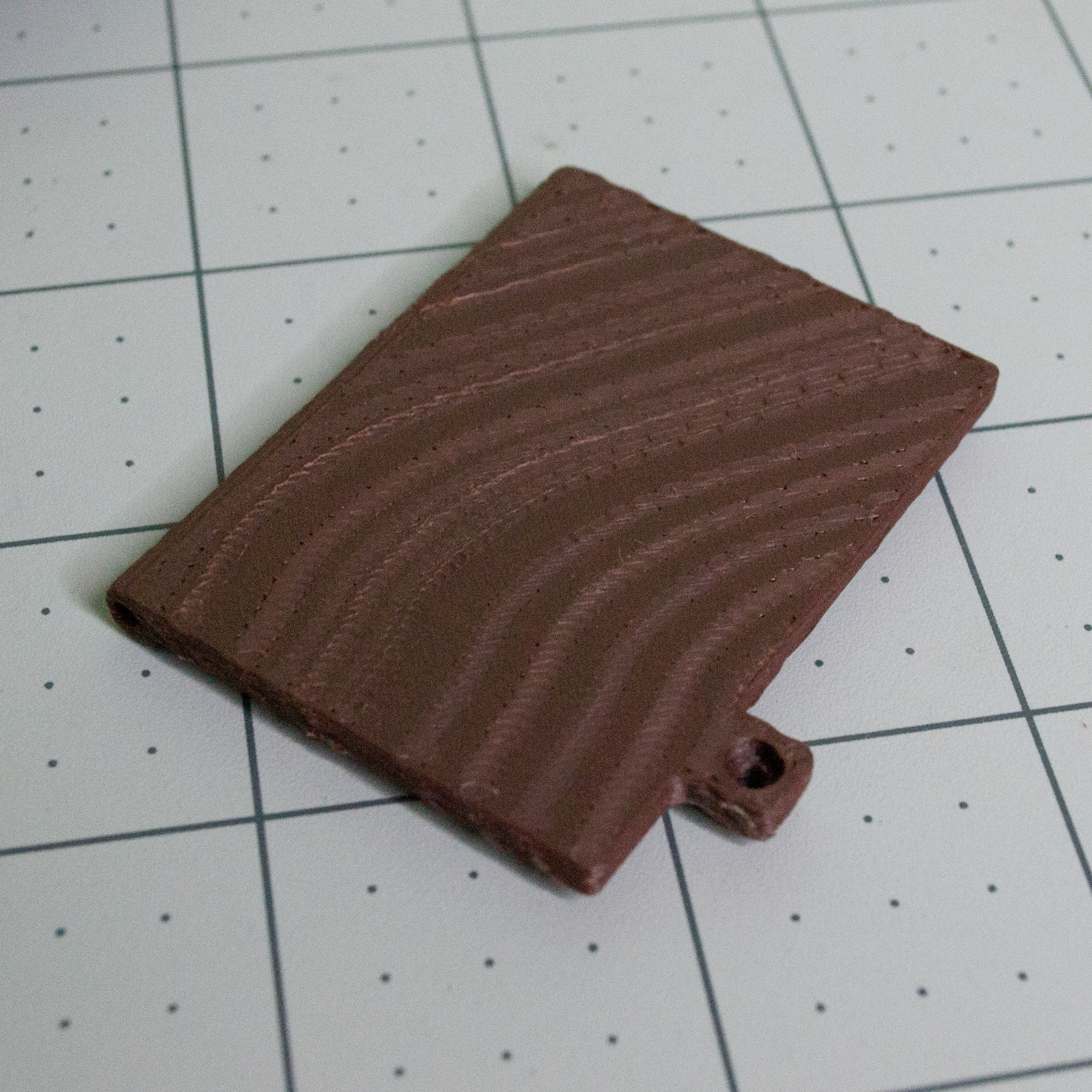 | Printed Lid | 1 | 3D printed from project files | Battery compartment lid. |
|
| Printed Lid | 1 | 3D printed from project files | Battery compartment lid. |
| 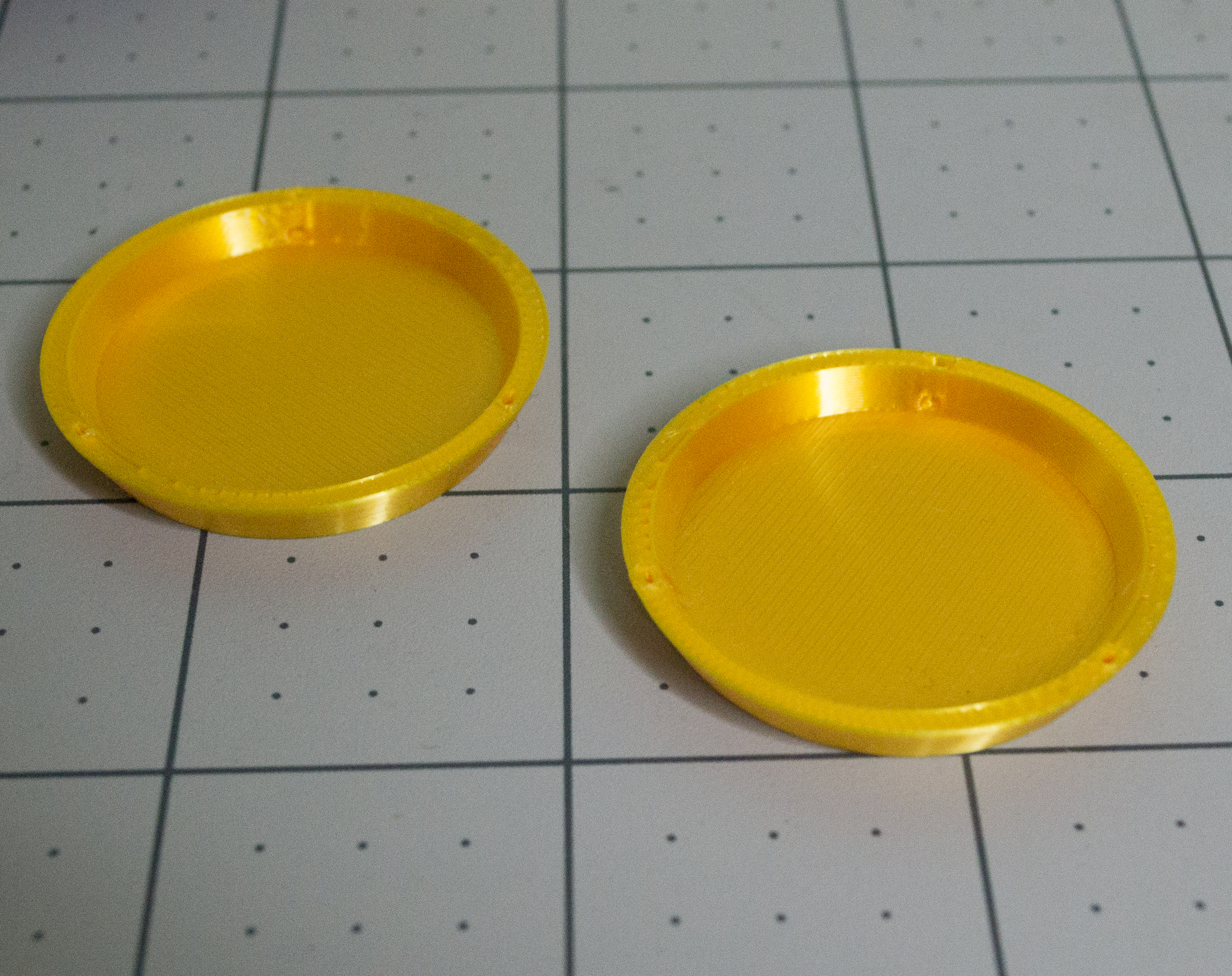 | Printed Plates | 2 | 3D printed from project files | Hanging scale plates. |
Tools
| Tool | Need | Notes | | - | - | - | | 3D printer | Required | Used to print the VintageScale parts. | | Phillips screwdriver | Required | Used for the M2 screws. | | Soldering iron | Required | Used to solder the capacitors, headers, battery contacts, and DC-DC converter. | | Solder | Required | Used for all PCB solder joints. | | Crimp tool | Required | Used to crimp the small and medium gold crimp beads onto the monofilament. | | Small flat-blade screwdriver | Required | Used to adjust the onboard potentiometers. | | Sandpaper | Recommended | Useful if printed parts fit too tightly. | | Tweezers | Recommended | Makes it easier to thread monofilament and place M2 hex nuts. | | Hammer | Recommended | Used to insert the threaded insert; a soldering iron can also be used. | | Small round tool or pick | Recommended | Helps keep the extra monofilament loop open while pushing small gold crimp beads into position. A small screwdriver, pick, or drill bit can work. | | Pliers | Optional | Helps break apart header pins. | | Drill with 2 mm bit | Optional | Useful if the filament hinge hole needs to be opened slightly. | | Scissors | Optional | Used to cut monofilament and the 1.75 mm filament hinge pin. |
Development
Overview
Before you begin the build, I want to talk about how VintageScale was developed. This section covers the original motivation, the design decisions behind the project, the software and simulation tools I used, the custom TwoPositionServo PCBA, the 3D model and lever design, the battery-powered system, and a few possible future project ideas.
Motivation
I often see projects built around microcontrollers when the final behavior does not really need a computer. Microcontrollers are powerful and useful, but they can also make simple projects feel over-engineered just because they are cheap, available, and quick to use. Using a microcontroller for this project would have allowed much more customizability, but there is something interesting about the analog nature of electronics: every part interacts with everything else, and it is especially rewarding when a circuit without a microcontroller works the way you intended.
Beyond the electronics side, I have never been a great gift giver. Whenever someone's birthday comes around, or when a new year begins, I often do not know what to give. I wanted to make a simple but meaningful decorative device that could be gifted to many different people. VintageScale is not just a mass-produced item. It takes time and effort to assemble, and the two objects or ideas placed on it can be chosen specifically for the person receiving it.
I have also showcased some of my projects at events. At my most recent showcase, VintageScale was used as a giveaway prize, and the winner happily received it.
My Innovations
Innovation is often described as something completely new to the world, but in the maker world, even small design decisions and personal breakthroughs can teach us something that cannot be learned from reading alone. Those moments come from experience, and they are worth being proud of.
For me, this was the first time ordering a printed circuit board with assembly instead of only ordering a bare PCB. A bare printed circuit board is usually called a PCB, while the assembled board with components installed is called a PCBA. In this project, the custom HexHands TwoPositionServo controller is a PCBA because many of the surface-mount components are assembled during manufacturing. It was nerve-racking to order because I had to double-check the footprints, verify the datasheets, and make sure the design files were correct before sending it out.
The AAA battery compartment was also a first for me. Instead of buying an external battery holder, soldering extra wires, and making the project larger, I decided to put the battery contacts directly on the controller board. This may seem small, but it gives me much more control over future designs because I can build the battery holder directly into the product instead of designing around an external part.
Finally, I am proud of the monofilament movement system. It can be difficult to tension correctly during assembly, but the final mechanism is simple and visually clean. There are no obvious rods or large internal linkages moving the Lever up and down. When everything is assembled, it almost feels like the scale is moving by itself, because the motor and linkage are mostly hidden.
Software Used
During this project, I used Tinkercad to simulate the early circuit behavior, Fusion 360 for the 3D modeling, and Fusion Electronics for the PCB design.
Simulation
Simulation was a big part of the early prototyping process. Tinkercad is very visual, which made it useful for quickly testing the basic logic and servo-control idea. Instead of immediately working with SPICE models in tools such as Fusion, KiCad, or LTspice, I could quickly experiment with the circuit and see how the simulated servo responded.
During the first few weeks, I developed the main control idea using three NE555 timers, an AND gate, and a NOT gate. I later built the physical version on a breadboard and refined the design in Fusion Electronics, but Tinkercad helped me simulate the PWM signal and servo movement while I waited for parts to arrive.
SPICE models are files that represent how electrical components behave in circuit-simulation software.
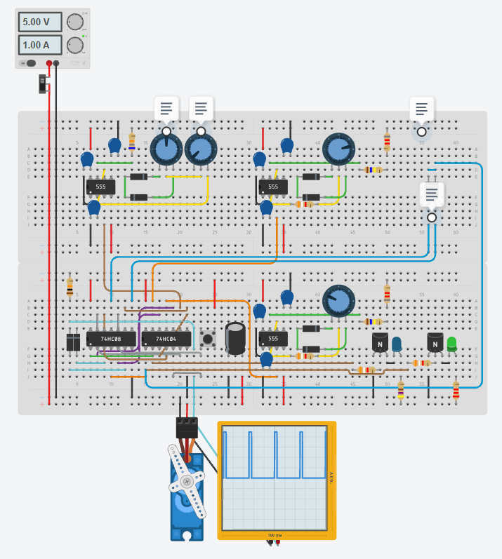
Tinkercad simulation of the TwoPositionServo control circuit.
TwoPositionServo test circuit built on a breadboard.
3D Design
The build is separated into two main mechanical assemblies: the Body and the Top/Scale assembly. The Body holds the TwoPositionServo PCBA, battery contacts, power controls, and battery compartment. The Top/Scale assembly holds the servo, Lever, decorative scale parts, and internal monofilament lines.
To make the PCBA fit cleanly with its controls, the Body was designed so the controller board can be placed inside first, and then the Bottom can slide into position over the controls on the back. The back side also has screw locations that work with the internal standoffs to make the assembly stronger and cleaner looking. For the battery lid hinge, I used a short piece of 1.75 mm filament instead of a screw-based hinge, because the lid needs to open repeatedly and screw heads would have been more visible.
The Top/Scale assembly was designed with disassembly and maintenance in mind. The servo and the monofilament tensioning system are contained in this section. To move the Lever above the scale mast, the servo pulls two monofilament lines. Those lines travel through a small internal hole up the mast, exit through the Lever, and are secured with small gold crimp beads. As the servo moves back and forth, one line is pulled slightly, which tilts the Lever in that direction.
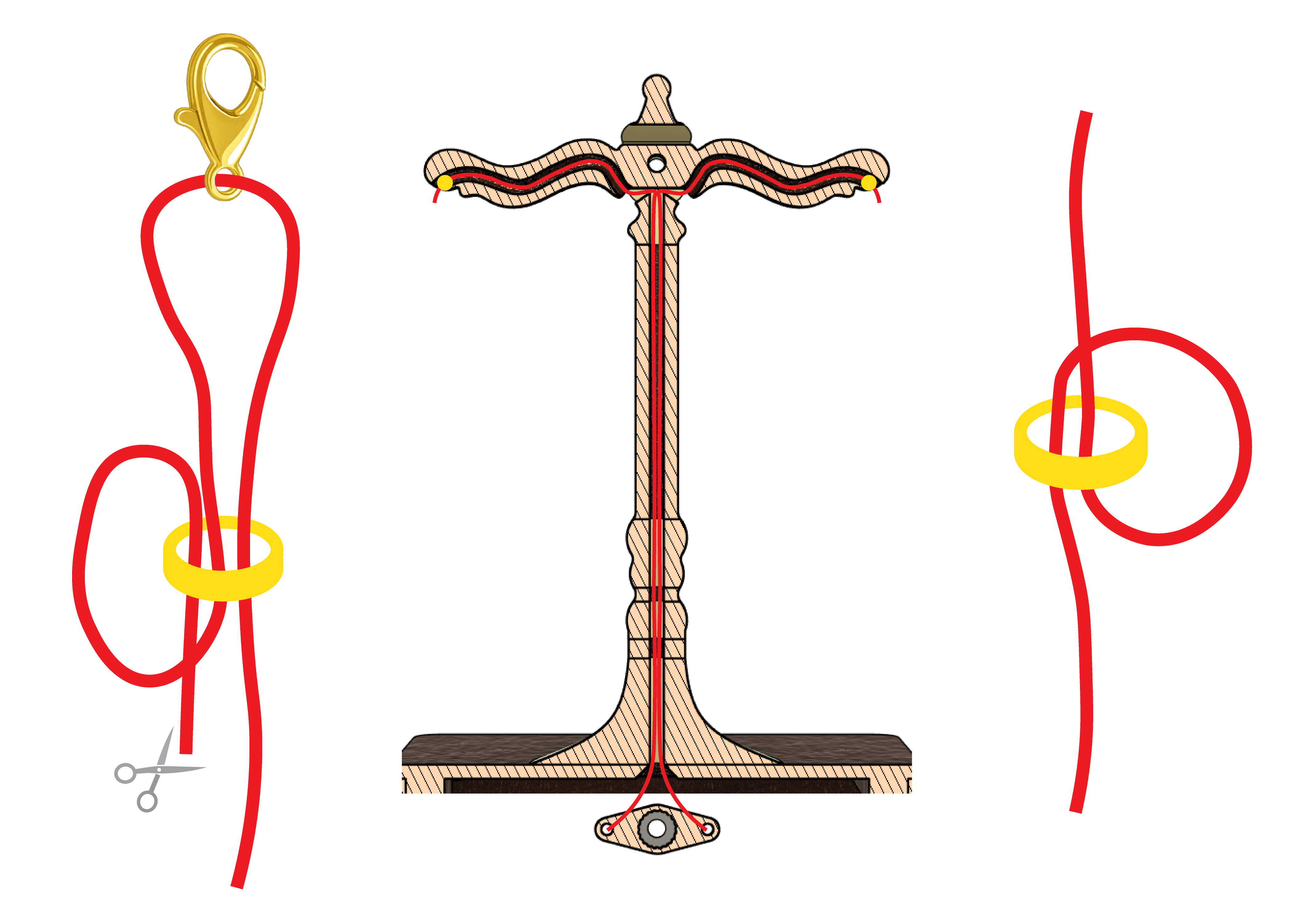
The left and right diagrams show how the monofilament line is looped through the small gold crimp bead so it does not slip. This detail is important because the mechanism depends on the monofilament staying tight and secure.
Battery Power
VintageScale uses three 1.2 V AAA rechargeable batteries connected in series, giving a battery voltage of about 3.6 V when charged. A QEBIDUM DC-DC boost converter steps this battery voltage up to the 5 V rail used by the controller board and micro servo.
I chose three AAA cells because the voltage is high enough for the boost converter to work efficiently, but still low enough for the converter to regulate upward to 5 V. As the batteries discharge, the converter continues boosting the voltage so the TwoPositionServo controller and servo can keep running from the 5 V rail.
The PCBA also includes a low-voltage detection circuit. When the battery voltage drops below about 3.08 V, the controller board shuts off and turns on a red LED to show that the batteries should be replaced or recharged.
Battery power matters for this project because VintageScale is meant to be displayed like a small decorative object. It can sit on a desk, shelf, or bookcase without needing to be near a power outlet or USB power supply.
Project Ideas
VintageScale was not the only idea I considered for the TwoPositionServo controller. I chose it because it had the best balance of depth, simplicity, and elegance. In terms of depth, it can represent ideas, priorities, and personal meanings. In terms of simplicity, it does not require a complicated gear mechanism that would take months to test. In terms of elegance, it can fit into many different spaces as a decorative object.
One alternate idea was a small farmland display. Different 2D plants, such as wheat, tomatoes, or corn, could periodically pop in and out of the ground to represent growth and harvest.
Another idea was a cow being abducted by an alien spaceship. This would have been more complicated, with the cow occasionally floating upward toward a small UFO.
There are many other projects that could be built from the same controller concept. A simple two-position servo movement can be used for small displays, signs, props, toys, mechanical indicators, or other battery-powered decorative objects. I hope VintageScale gives you ideas for your own version.
Custom Circuitry on the Board
Overview
Here I will talk about the general design of the custom circuit board created for this project. How was it done without a microcontroller?
Main ICs and Circuit Blocks
The board is built around a few main circuit blocks:
| Circuit Block | Purpose | | - | - | | NE555 Timer IC | Creates the switching signal and the 50 Hz PWM-style signals servos require to move to specific positions. | | AND Gate IC | Enables and disables PWM signals coming from two NE555 timer chips based on what position the servo should be in. | | NOT Gate IC | Used to flip the position-indicating NE555 timer signal and help clean up PWM signals. | | Potentiometer | Adjusts the cycle time, time proportion, and two servo positions using specifically set up potentiometer resistances. | | DC-DC Boost Converter | Boosts low voltages to the 5 V used by the custom board. | | Low-voltage Detection | Turns the circuit off when voltage is lower than 3.08 V. | | Selection Switches | Let the board run from USB or battery. | | Capacitors | Filter out power supply noise and support timing behavior. |
Basic Signal Flow
At a high level, the circuits on the board work like a chain of lots of small circuits and decisions. We can start with the cycle timer that decides what position the servo should be set to. This cycle timer can be adjusted to change the total time and the proportion of time the servo spends in each position.
Next, we have two PWM timers which constantly create signals as if they are both sending them to the servo. Then, using the AND and NOT gates, we take the output of the cycle timer and decide which signal we should push through to the servo. One side does an AND operation on the cycle timer and one PWM signal. The other side does an AND operation on the inverted cycle timer and the other PWM signal. Those are then ORed together into a single line that is sent off to the servo. This overall describes the main circuitry of this board in simple terms. If you are interested, you can learn more below.
Timers
The NE555 is a classic timer IC. It can be used for a variety of things, from basic time delays and repeating oscillations depending on how external resistors and capacitors are connected, all the way up to voltage comparison and toggle switches. The NE555 is the older version of the 555 timer, which runs on a bipolar system. Bipolar means that bipolar junction transistors are used to create the output. New chips like LMC555, TLC555, and TS555 improve mainly on power consumption, higher top speeds, and CMOS. The main change we want to look at is CMOS.
CMOS stands for Complementary Metal-Oxide-Semiconductor, which is how the vast majority of chips are created today. They work on the basis of NMOS and PMOS transistors, similar to NPN and PNP transistors. The reason our circuit uses an NE555 timer is due to using it in a motor-control project where I wanted a strong and durable signal source. CMOS-based timer chips often max out at 10 mA to 50 mA of output current. This means that they are not always the best choice when I want a stronger control signal with extra margin. The NE555 does not power the servo motor directly. The servo gets its motor power from the 5 V rail, while the NE555 helps create a strong timing/control signal. The higher output-drive capability of the bipolar NE555 gives the signal more margin than many low-power CMOS timer variants, which is useful in a DIY circuit with connectors, wires, and other logic stages. In this case, the high current capability of the NE555 acts as a buffer, allowing the control pulse to travel through the circuit with less electrical interference. Additionally, it is harder to break, which is perfect for our DIY usage.
The TwoPositionServo board utilizes three NE555 timer chips. One chip has a slow timer that ranges from around 20 seconds to 2 minutes depending on how you set the potentiometer. This timer gives a clean one or zero output which tells us which LED should shine and what position the servo should be in. The other two timers are used for creating the 50 Hz PWM signals for the hobby servo. For those, the capacitance and resistance have been set up so that the raw timer output is a high-duty-cycle signal of about 89% to 98%. However, since we later use other ICs to clean up and invert the signal, the useful servo-control pulse becomes the shorter part of that waveform, which is closer to the timing range hobby servos use for position control.
For the PWM, I use the NE555 timer in astable mode, meaning that it repeatedly charges and discharges the capacitor. Specifically, it does not require external inputs like button presses to start, so astable essentially repeats forever, unlike monostable mode, which creates one timed pulse after being triggered.
We can calculate the high time, low time, period, and frequency of this chip using the values I have used.
RA = 168.2 kΩ > 168200 Ω
RB = 3.9 kΩ + potentiometer value (from ~0 Ω to ~20 kΩ) > 3900 Ω + potentiometer value (from ~0 Ω to ~20000 Ω)
C = 150 nF > 0.000000150 F
Use the following units in the formulas:
Resistance: ohms, Ω
Capacitance: farads, F
Time result: seconds, s
Frequency result: hertz, Hz
| Name | Formula | Calculation | | - | - | - | | High Time | 0.693 (RA + RB) C | 0.01789 to 0.01997 seconds | | Low Time | 0.693 RB C | 0.000405 to 0.002484 seconds | | Period | High Time + Low Time | 0.01830 to 0.02245 seconds | | Frequency | 1 / Period | 44.537 to 54.659 Hz |
The images below show one of the NE555 astable timer circuits used to create the PWM-style timing signal. In this part of the circuit, changing the potentiometer changes the timing relationship between the high and low portions of the waveform.
One important detail is that this signal is later inverted and cleaned up by the logic section of the controller board before it is sent to the servo. That is why the waveform shown here looks like a very high-duty-cycle signal. After the later circuit stages, it becomes a more useful servo-control pulse.
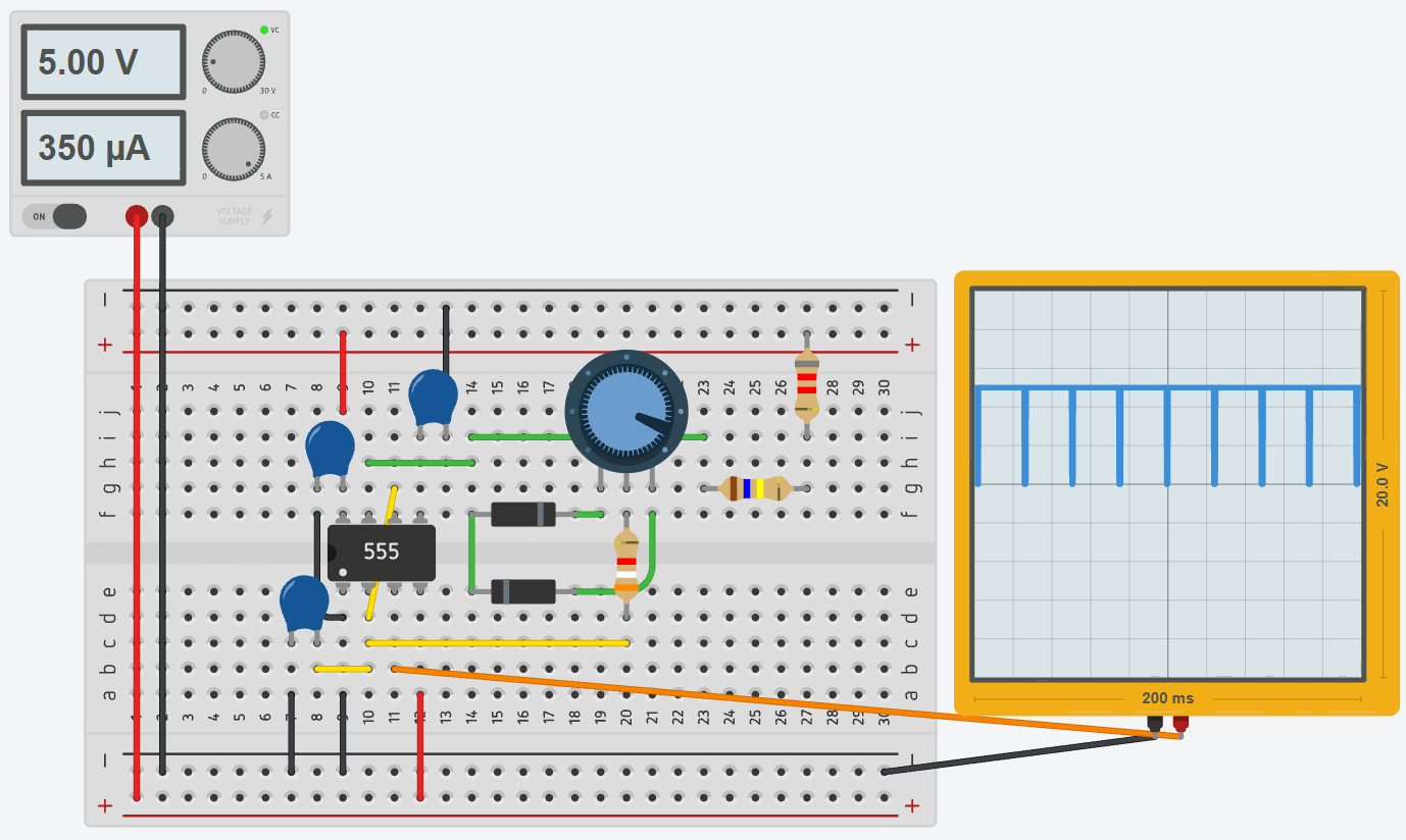
Potentiometer near 20 kΩ. The low-time portion increases, changing the period and duty cycle.
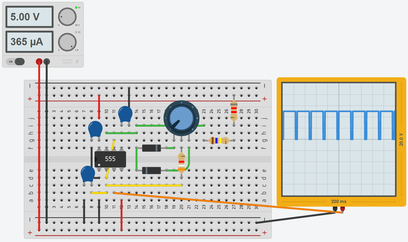
Potentiometer near 0 Ω. The low-time portion is shorter, which shifts the timing toward the other end of the adjustment range.
The close-up below shows the values used in the astable timer circuit. The fixed resistor, potentiometer, and capacitor control how quickly the capacitor charges and discharges. That charge/discharge cycle is what creates the repeating waveform.
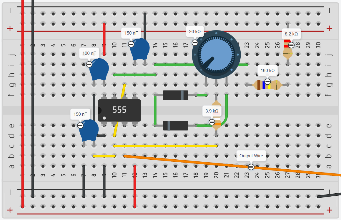
The animation below shows the potentiometer being adjusted while the waveform changes. This was useful during prototyping because it made the relationship between the component values and the servo timing much easier to understand visually.
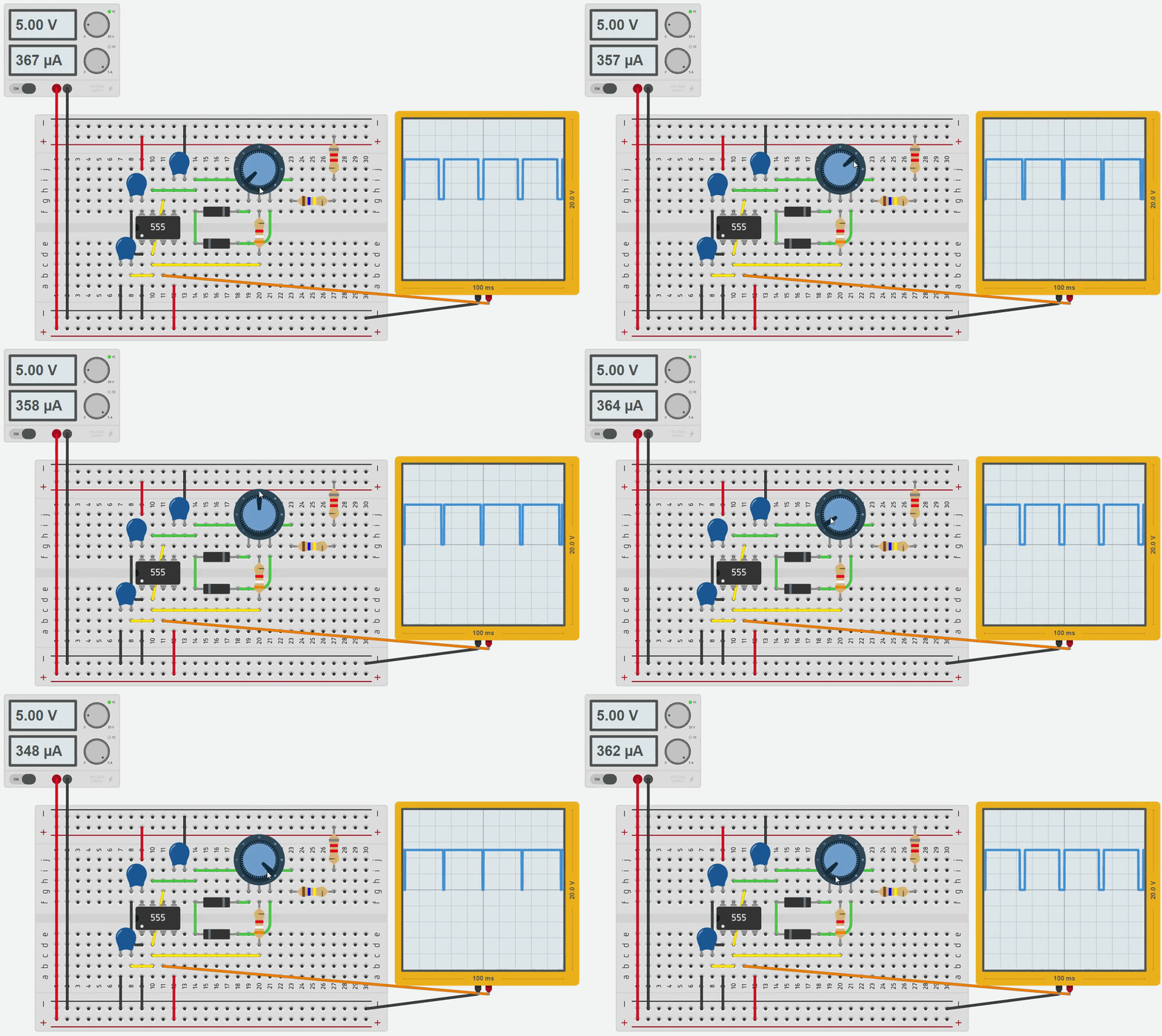
In the TwoPositionServo controller board, this timing section works with the logic ICs and the other NE555 timers to select between two servo positions. The result is a no-programming servo controller where the timing and positions can be adjusted directly from the board.
Emulating XOR
More recent versions of the TwoPositionServo board include a debug button that, when clicked, flips the current servo stage. We do that by doing an XOR operation. XOR essentially outputs a one if either input is a one, but not both. Below is a truth table.
| A | B | Out | | - | - | - | | 0 | 0 | 0 | | 0 | 1 | 1 | | 1 | 0 | 1 | | 1 | 1 | 0 |
Using XOR, we can take inputs from both the timer that indicates the servo position and the button. If we get both inputs as a zero, which means the button is not pressed and the servo should be in one position, then we receive an output of zero indicating the servo will be in its first position. If both inputs get a one, where the button is pressed and the timer says the servo should be in position two, the XOR output becomes zero. This means the button has flipped the original timer position back to position one. In other words, pressing the button temporarily reverses whichever position the timer selected.
However, this board does not have an XOR IC onboard, and incorporating it would require another component which costs money. Additionally, we were left with two NOT gates and two AND gates. Utilizing those open gates and a makeshift OR from two diodes facing the same direction, we were able to create XOR.
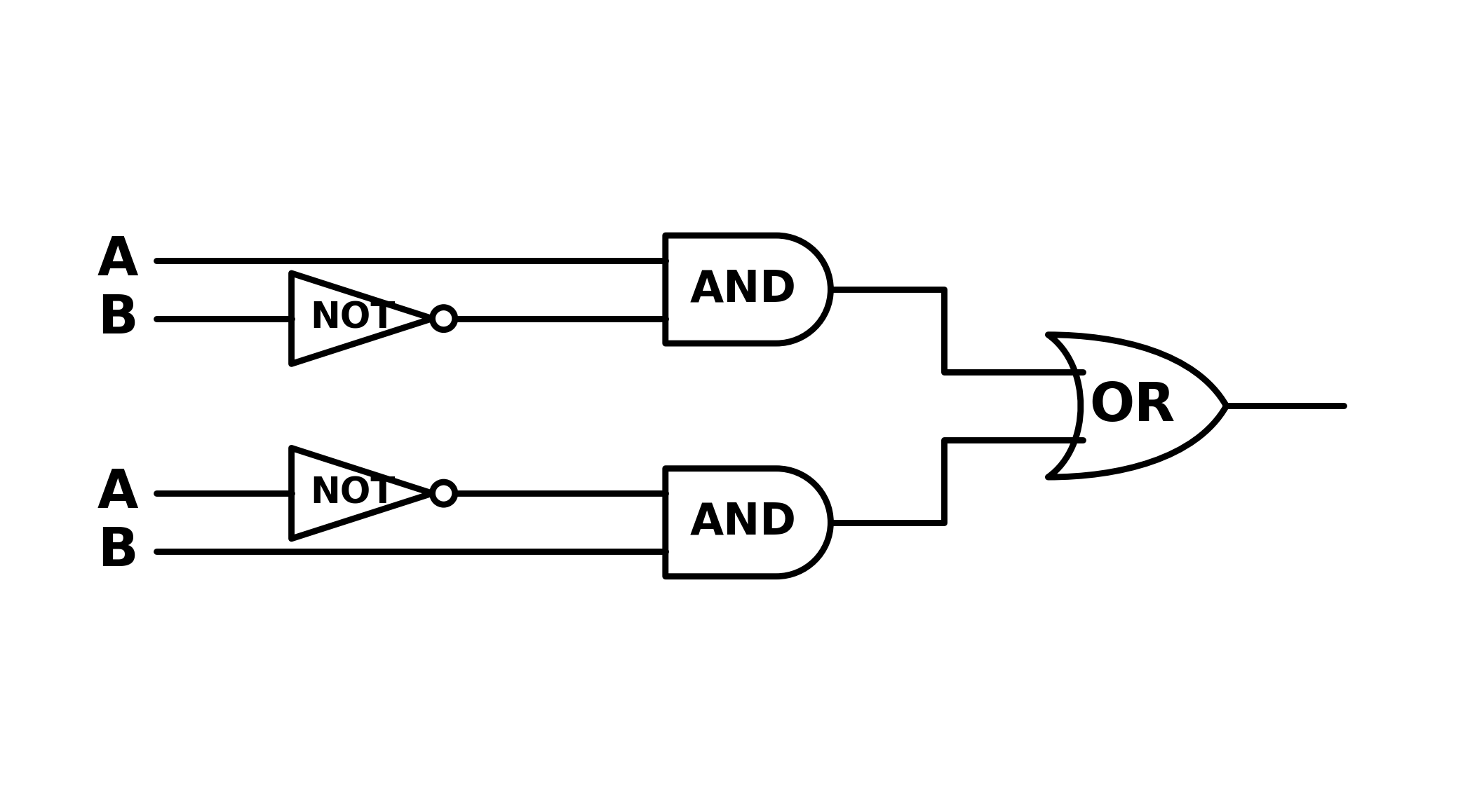
3D Printing the Parts
Overview
For slicing, I used Bambu Studio, but other slicers with similar multi-part import support, such as OrcaSlicer or PrusaSlicer, should also work.
This project consists of 7 main printed components, or 8 physical printed parts because the Plate is printed twice. Some components use multiple files that should be imported together so the color-separated parts stay aligned correctly.
Materials and Files
| Item | Qty | Notes | | - | - | - | | Bambu Lab PLA Wood Rosewood | As needed | Main wood-color filament. Source: https://store.bambulab.com/products/pla-wood?id=43075831988360 | | Bambu Lab PLA Silk+ Gold | As needed | Gold accent filament. Source: https://store.bambulab.com/products/pla-silk-upgrade?id=43128679792776 | | Transparent PETG | Small amount | Used for the status-light window. White filament can also work if you do not have transparent PETG. Source: https://store.bambulab.com/products/petg-translucent?id=42235108098184 | | 3D printer | Required | I used a Bambu Lab X1C with Bambu Studio for slicing, but other printers should work if the parts fit and are sliced correctly. |
| File | Link |
| - | - |
| VintageScale.arm | https://a360.co/4b1msDe |
| VintageScale.bottom | https://a360.co/4f1erPZ |
| VintageScale.case | https://a360.co/4p6T5p6 |
| VintageScale.lever | https://a360.co/3RjQT0N |
| VintageScale.lid | https://a360.co/4geFR7d |
| VintageScale.plate | https://a360.co/4eRmz5l |
| VintageScale.scale.gold | https://a360.co/4eRmA9p |
| VintageScale.scale.wood | https://a360.co/3SIA2oP |
| VintageScale.text | https://a360.co/4wreoUL |
| VintageScale.top | https://a360.co/4fgFrw4 |
| VintageScale.transparent | https://a360.co/4wlVePV |
| VintageScale.case.generalPLA | https://a360.co/3T3yp5a |
| VintageScale.lid.generalPLA | https://a360.co/4aAviI4 |
| VntageScale.top.generalPLA | https://a360.co/3QXwSgu |
Use the *.generalPLA extension when using PLA filament for the specific parts provided.
| Image | Component | Print Qty | Files to Import | Suggested Filament | Note |
| - | - | - | - | - | - |
| 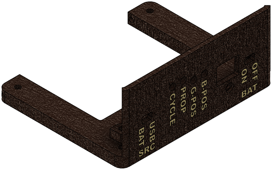 | Bottom | 1 |
 VintageScale.bottom + VintageScale.text | Wood (bottom) + Gold (text) | Text may be printed in a different color, or set to the same filament to ignore. Print text face touching the plate. |
| 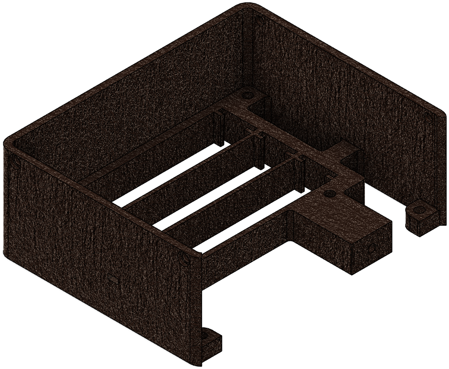 | Body | 1 |
 VintageScale.case + VintageScale.transparent | Wood (case) + Transparent PETG or white filament (transparent) | The transparent piece lets status lights show through. Use white filament if you do not have transparent PETG, or omit it for an open window. |
| 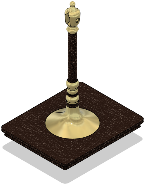 | Top/Scale | 1 |
 VintageScale.top + VintageScale.scale.gold + VintageScale.scale.wood | Wood (top + scale.wood) + Gold (scale.gold) | Import together as one grouped object. Requires supports. It can be printed separately without supports, but that will make the thin sections weaker. |
| 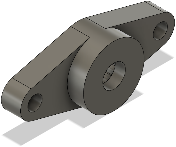 | Arm | 1 |
 VintageScale.arm | Any filament; PLA recommended | Filament expansion may affect the servo grip. |
| 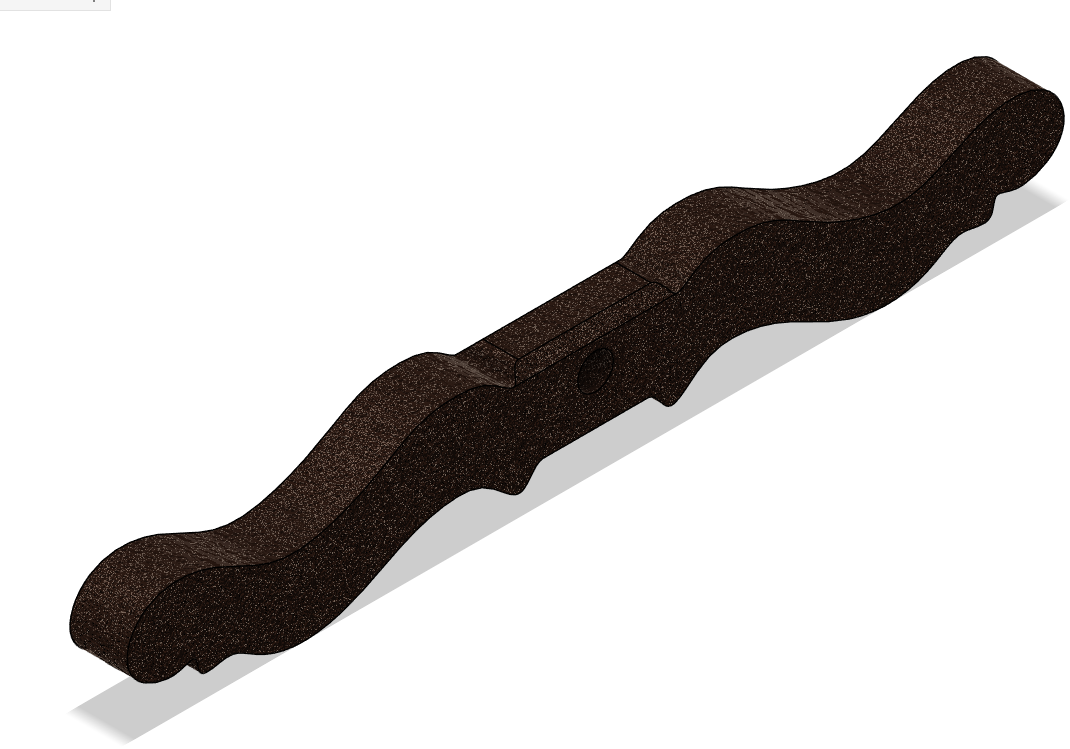 | Lever | 1 |
 VintageScale.lever | Wood | Intended to match the vintage scale look. |
| 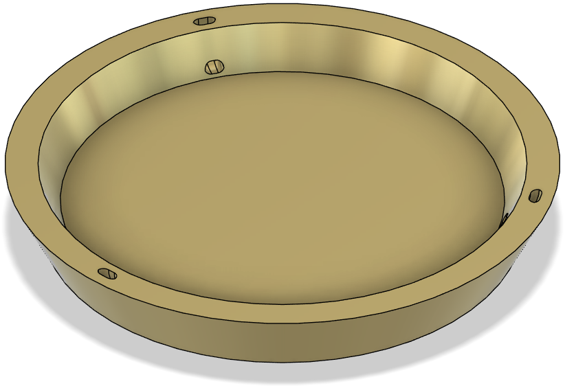 | Plate | 2 |
 VintageScale.plate | Gold | Print this part twice. |
| 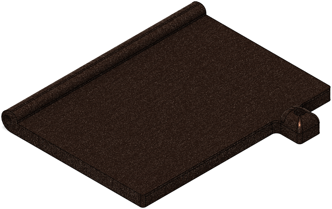 | Lid | 1 |
 VintageScale.lid | Wood or Gold | Choose whichever color looks best for your build. |
Note that all filament choices are aesthetic and can be changed. However, different filaments expand differently and have different material characteristics. The filaments I used have been tested with this design, so they will likely work best for this version of the project.
Steps
Importing Parts
Import each component into the slicer. You can place multiple components on the same plate, but you may need to split them across multiple plates depending on your printer and filament setup. For components with multiple files, select all related files and drag them into the slicer at the same time. If done correctly, the following popup should appear.
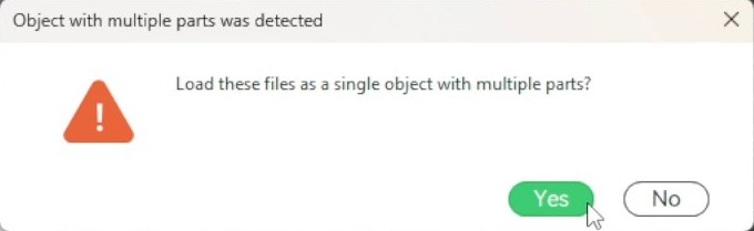
Click Yes to align the parts together. After that, to change the filament for each part, click Objects in the Process tab and then click the filament box for that part.
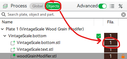
Adding Wood Grain
The wood-grain modifier is optional. If you want the simplest build, you can skip the wood-grain steps and print the parts normally using the filament colors in the table.
When using wood filament, you can make it look better by adding a real wood grain. This can make the printed wood parts look more realistic and aesthetic. Here I use the 3D model and tutorial provided by PandaN on MakerWorld. You can download the STL model here.
The following settings are based on a 0.4 mm nozzle with standard flow using the default preset named 0.20mm Standard @BBL X1C. If something does not work, check PandaN's MakerWorld instructions as well. This technique can be finicky, so it is worth testing on a small part first.
To use this method, first click on the model you would like to give the grain to.
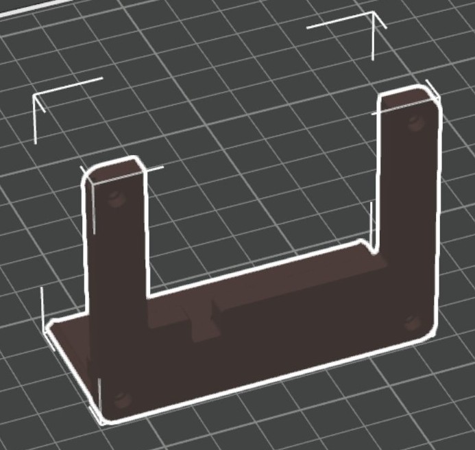
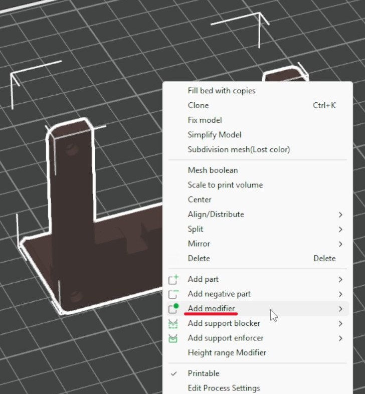
Next, right click on it and select "Add modifier", and then hit "Load". Following that, select the STL file that we downloaded.
A large translucent yellow log should appear on the plate. Resize, rotate, and move the log so that the whole component is engulfed.
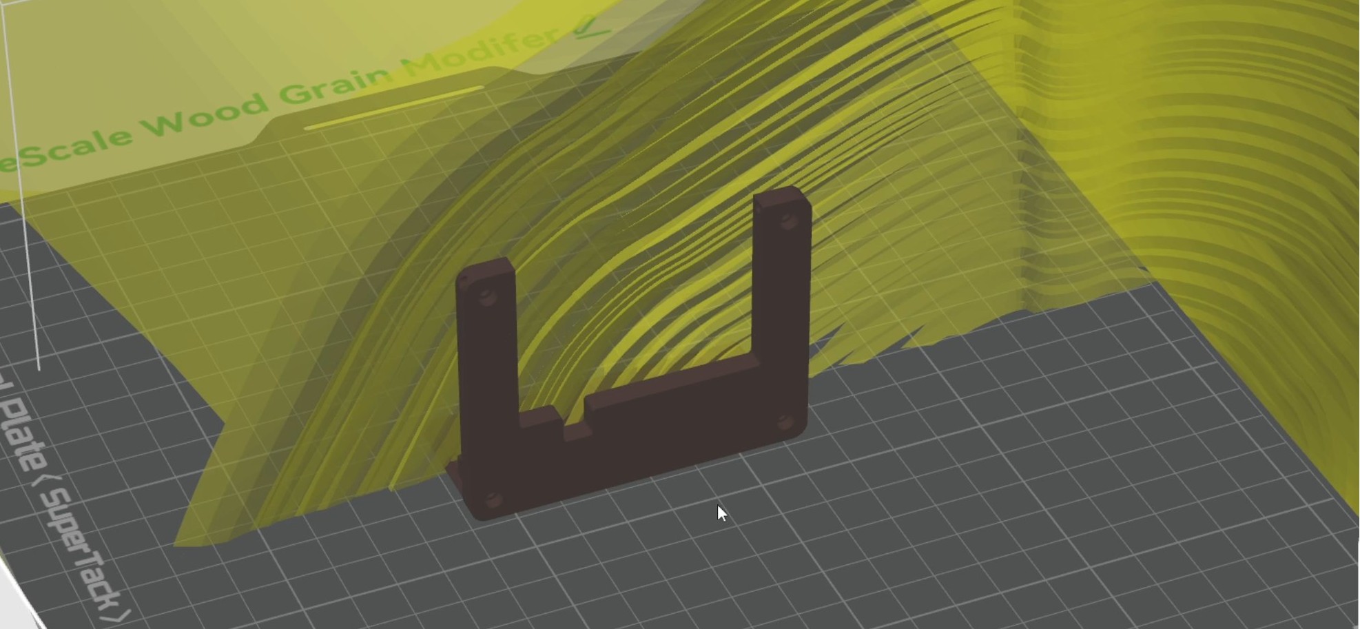
The result should look something like this.
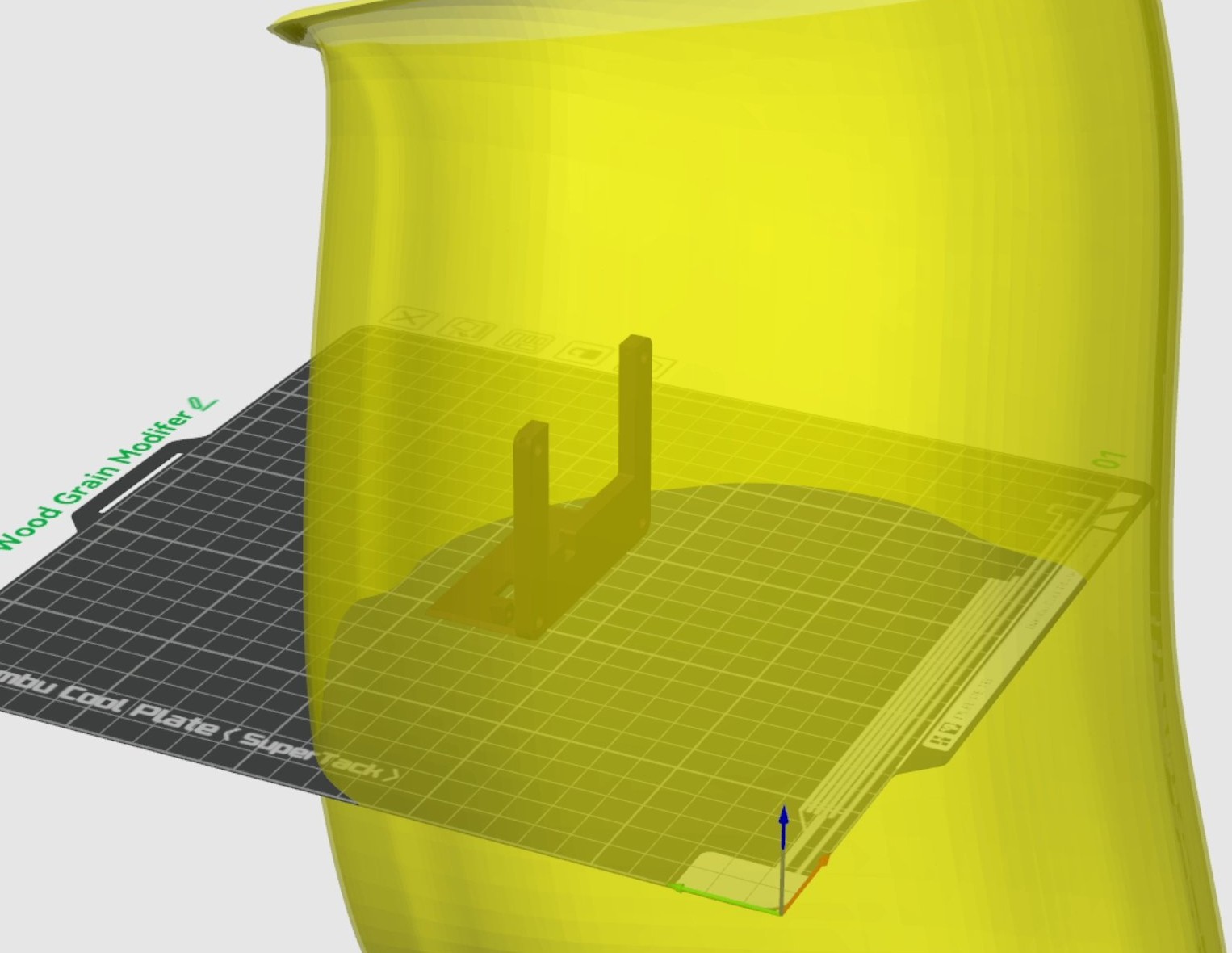
Different sizes, rotations, and positions can influence the end result. It is recommended to play around with placement before printing since you can come up with some unique grains.
Now, select the yellow log and make sure you have "Objects" selected in the "Process" tab. Now you can change the modifier settings. Right below the "Process" tab, you will see the following: "Frequent", "Quality", "Strength", "Speed", and "Others". We will change settings in Quality, Strength, and Others.
| Tab | Setting | Change to | Notes |
| - | - | - | - |
| Quality | Outer wall | 0.4 mm | Sets the line width for the visible outside walls. |
| Quality | Inner wall | 0.4 mm | Sets the line width for the inside wall paths. |
| Quality | Top surface | 0.4 mm | Sets the line width for top-facing surfaces. |
| Quality | Sparse infill | 0.4 mm | Sets the line width for regular internal infill. |
| Quality | Internal solid infill | 0.4 mm | Sets the line width for solid internal layers below top/bottom surfaces. |
| Strength | Top surface pattern | Aligned Rectilinear | Makes the top surface use straight, aligned paths. |
| Strength | Bottom surface pattern | Monotonic | Orders bottom surface lines consistently for a cleaner surface. |
| Strength | Infill direction | 135 | Rotates the line direction, which changes the wood-grain direction. |
| Others | Fuzzy Skin | Contour | Applies the texture to the outer contour walls. |
| Others | Fuzzy skin point distance | 0.1 mm | Controls the average spacing between surface texture points. |
| Others | Fuzzy skin thickness | 0.16 mm | Controls how far the texture can perturb the wall path. |
Additionally, in "Global" settings, I recommend changing Seam position to Random to make the print look more natural.
Now slice the model. When you zoom into the sliced preview, you should see small rough areas that form the wood-grain texture. Make any other print adjustments you need, then send the plate to the printer.
You will know that you correctly changed Seam position if you see white balls sprinkled around. If you don't, try to enable Seams in Display in the "Slicing Result" tab.

Now you are ready to print! Decide which models to print together, check the filament assignments, and start printing.
Controller Board Assembly
Overview
While the 3D printer is working, we can solder the controller board. In this section, we will add the electrolytic capacitors, battery contacts, headers, and boost converter board.
Materials
| Item | Qty | Notes | | - | - | - | | HexHands TwoPositionServo controller PCBA | 1 | Main assembled controller board. | | QEBIDUM DC-DC converter | 1 | Boost converter for the battery supply. | | Battery dome contacts | 3 | Positive battery contacts. | | Battery spring contacts | 3 | Negative battery contacts. | | 3-pin male header | 2 | One for the servo connector and one for the converter board. | | 2-pin male header | 1 | Used with the converter board. | | 47 uF capacitor | 1 | Install with correct polarity. | | 470 uF capacitor | 1 | Install with correct polarity. | | Soldering iron and solder | 1 set | Used for all PCB solder joints. |
Steps
Start by laying out the parts as shown. Pay close attention to capacitor value and polarity. In the image, the 470 uF capacitor is on the left, with its longer positive leg placed on the side marked with a plus sign. The 47 uF capacitor is on the right, also with its longer positive leg placed toward the plus sign on the controller board. When soldering these capacitors, insert the longer leg into the hole marked with the plus sign. Also solder one 3-pin male header on the top side of the controller board with the short legs going into the board. This is where the servo will connect later.
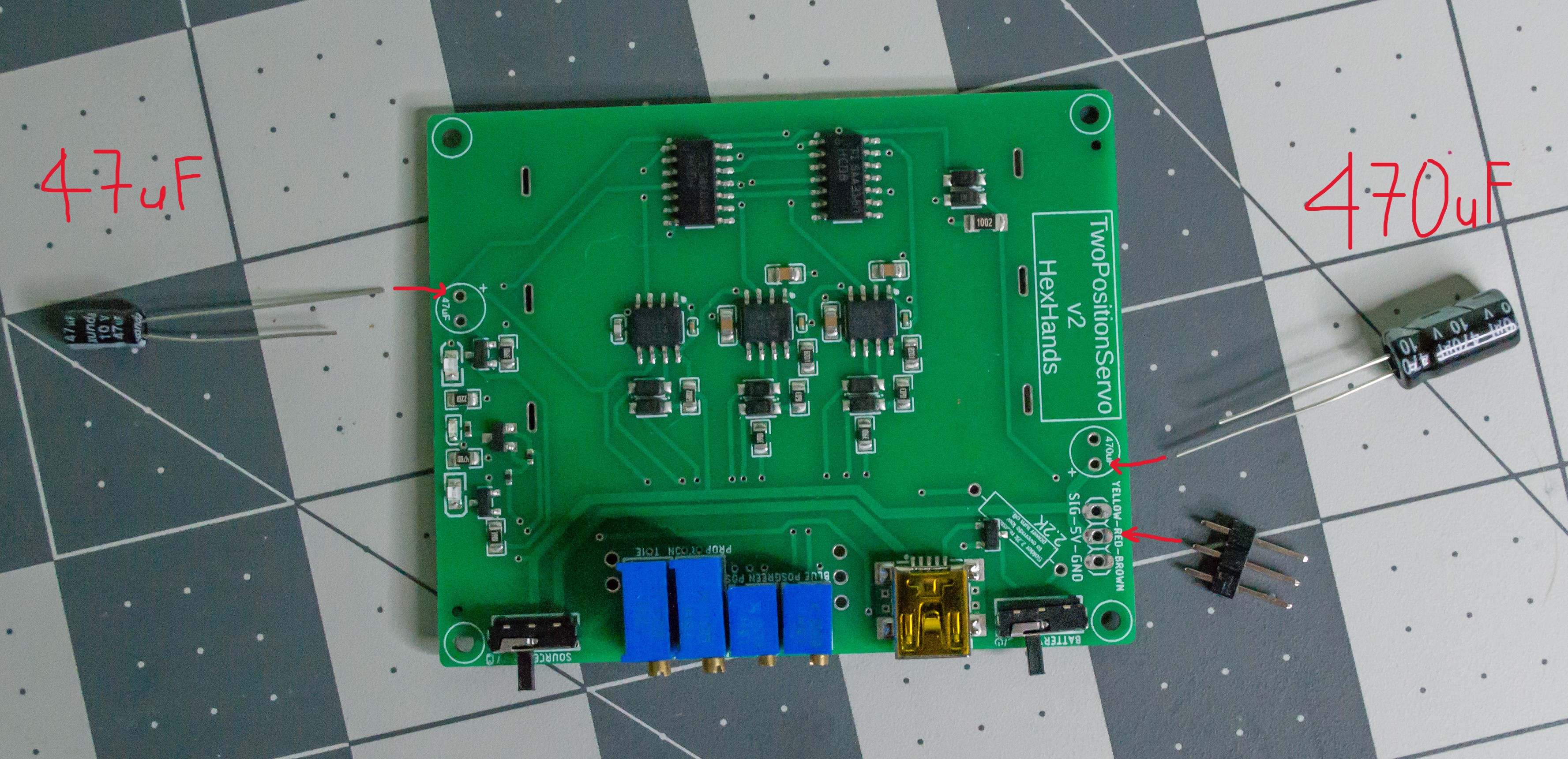
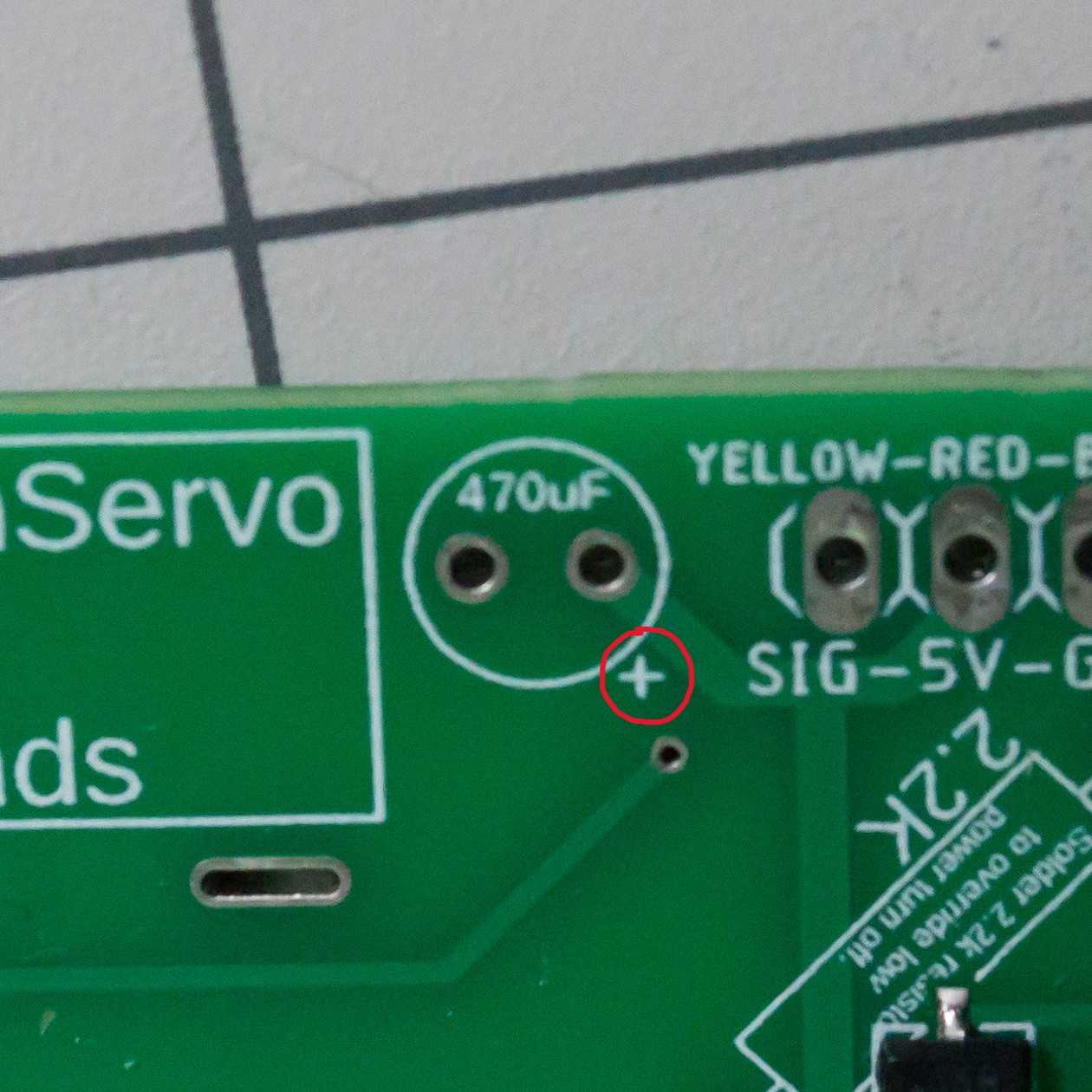
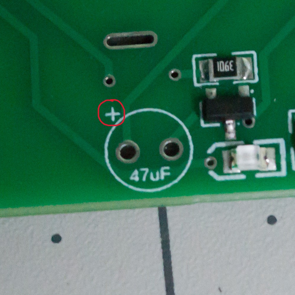
Solder those three components, then flip the PCBA over. On the back side, solder the battery contacts. The spring contacts go on the negative side, and the dome contacts go on the positive side with the raised side of each dome facing inward. It should look something like this.
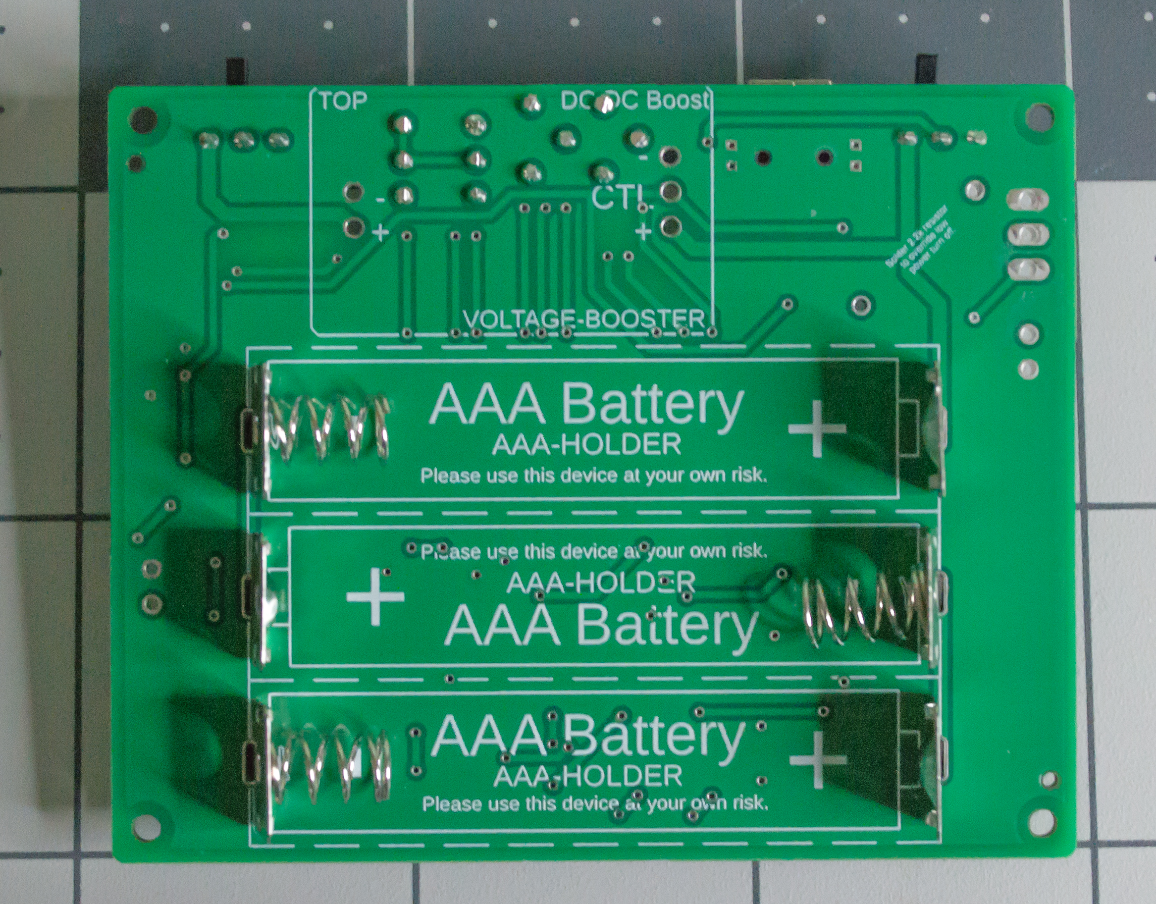
For these battery contacts, I recommend applying solder from the top side of the controller board. This keeps solder buildup away from the battery side, which helps the board sit properly during assembly.
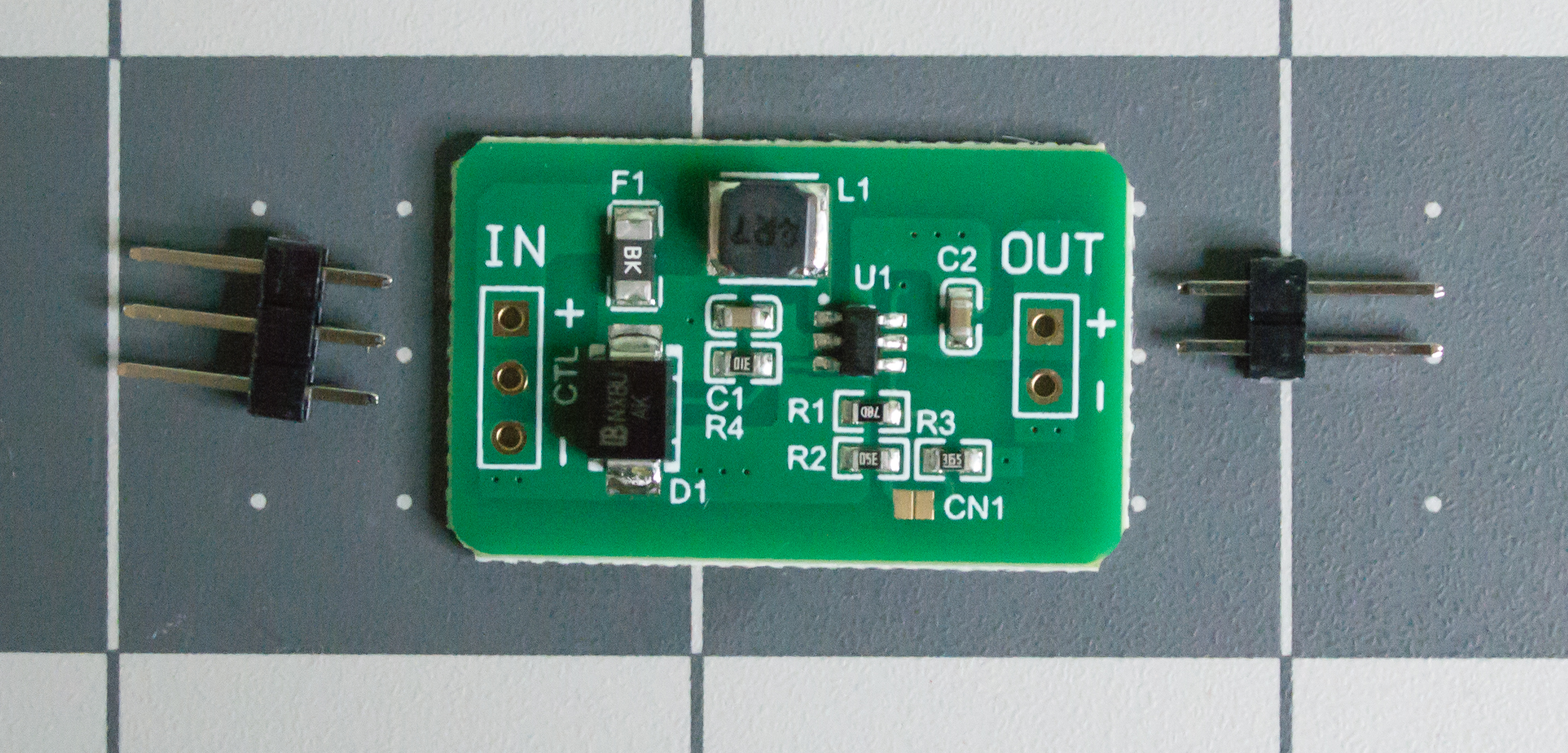
To prepare the QEBIDUM DC-DC converter, use one 3-pin male header and one 2-pin male header. Insert the short side of the pins into the converter board so the longer pins point downward. Then solder the pins to the converter. A breadboard can help keep the headers straight and correctly spaced while soldering.
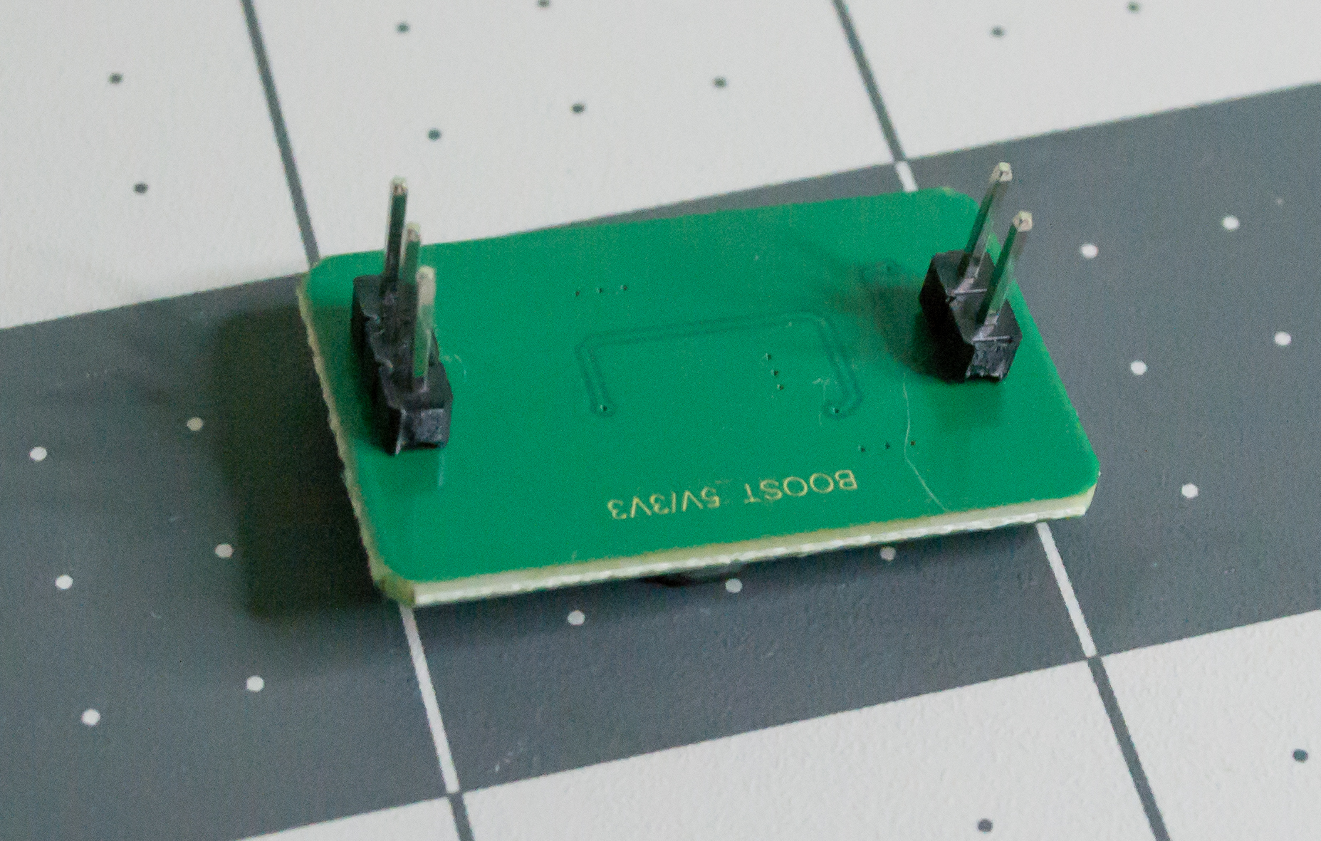
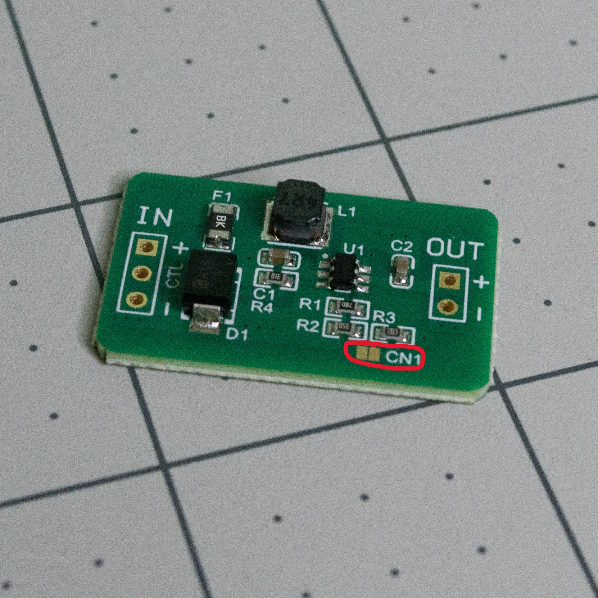
Place the converter board onto the main PCBA and solder it in place. Since this circuit runs from 5 V, bridge the CN1 pad on the converter board with solder so it steps the battery voltage up to 5 V.
Check: With three charged AAA rechargeable batteries installed, set
SourcetoBATandBatterytoON. The board should power up without a USB cable connected, and the servo should move.
The resulting PCBA should look like this.
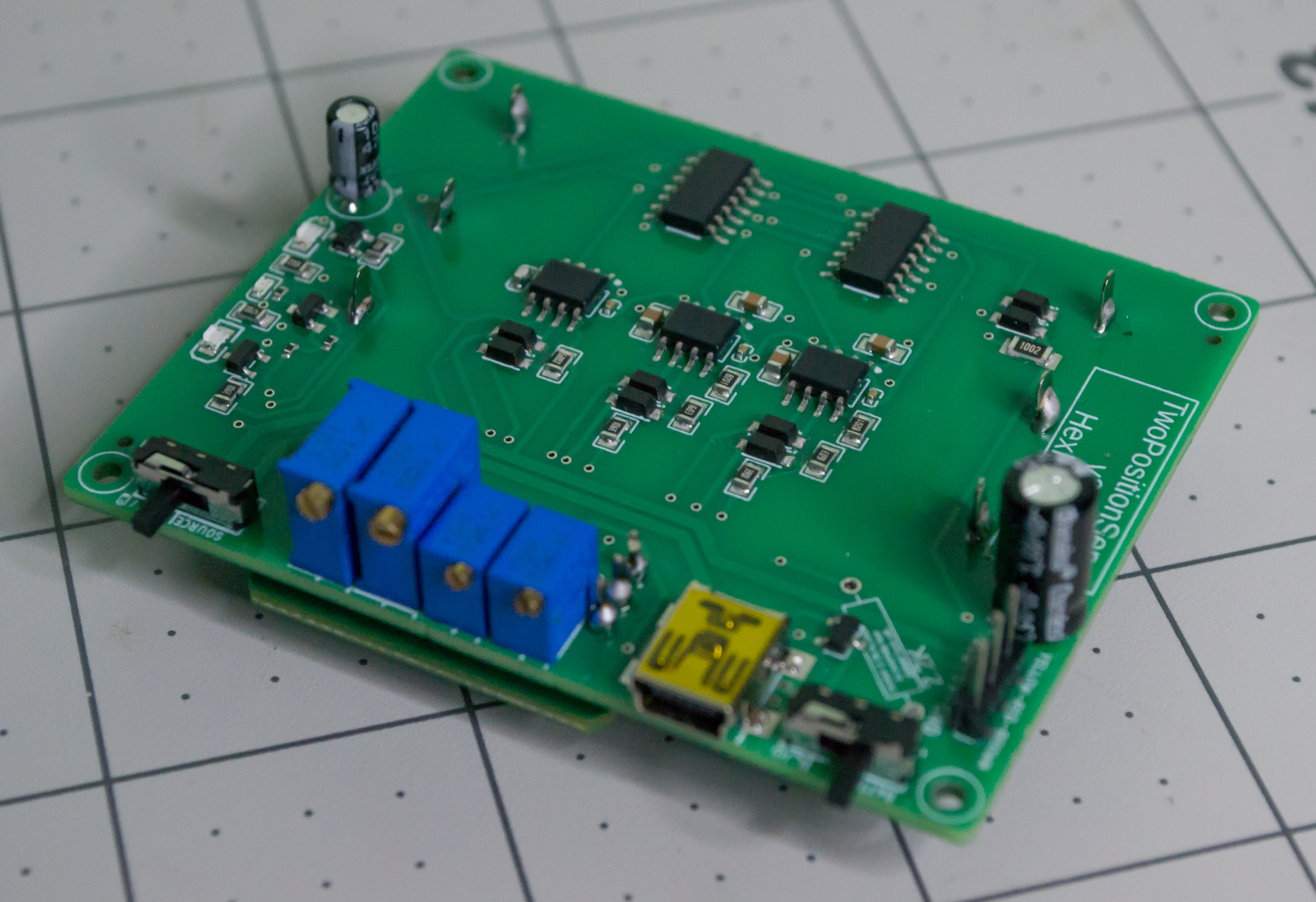
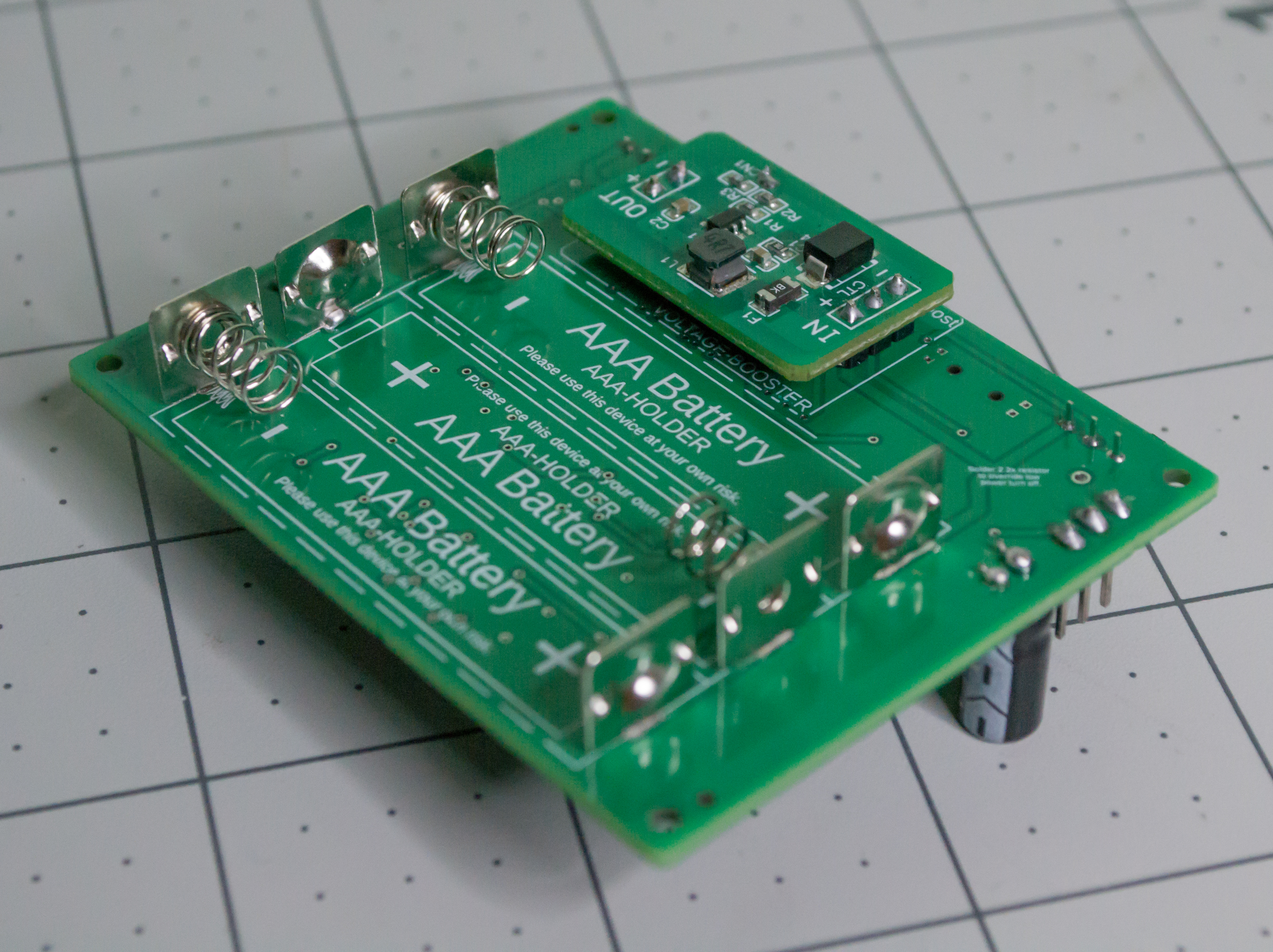
Mechanical Assembly
Overview
Now that the main printed and electronic parts are ready, we can assemble VintageScale. This section uses the printed parts, monofilament, hardware, servo, and assembled controller board.
Materials
| Item | Qty | Notes | | - | - | - | | Assembled TwoPositionServo controller PCBA | 1 | Completed in the previous section. | | Printed Body | 1 | Main body shell. | | Printed Bottom | 1 | Slides into the body and supports the PCBA. | | Printed Top/Scale | 1 | Holds the servo, lever, and scale mast. | | Printed Arm | 1 | Presses onto the servo output shaft. | | Printed Lever | 1 | Moves from the monofilament linkage. | | Printed Lid | 1 | Battery compartment lid. | | Printed Plates | 2 | Hanging scale plates. | | Micro servo | 1 | I used the Miuzei MS18 9 g servo. | | Monofilament line | As needed | Used for the linkage and hanging plates. | | 1.75 mm filament piece | ~7.5 cm | Used as the battery-lid hinge pin. I used transparent PETG, but any straight 1.75 mm filament piece should work. | | Small gold crimp beads | 12 | Used to lock the monofilament loops. | | Medium gold crimp beads | 2 | One for each hanging plate assembly. | | Folded clamshell bead tips | 2 | Decorative cover pieces for the Lever lines. | | Gold lobster claw clasps | 2 | Used to hang the Plates from the Lever. | | M2 hex nuts | 8 | Four for the PCBA/body, two for the servo, two for the fulcrum. | | M2, 16 mm machine screws | 5 | Four for the body/PCBA stack and one for the fulcrum. | | M2, 12 mm machine screws | 2 | Used to mount the servo. | | M2, 8 mm machine screws | 6 | One for the battery lid, four for the top/body, and one for the back. | | Servo horn screw | 1 | Holds the printed arm onto the servo shaft. | | Brass heat-set threaded insert | 1 | Threaded insert for the battery lid screw. | | 1.2 V AAA rechargeable batteries or USB Mini-B power | 3 batteries or 1 cable | Used to power the finished build. |
Body and Battery Compartment
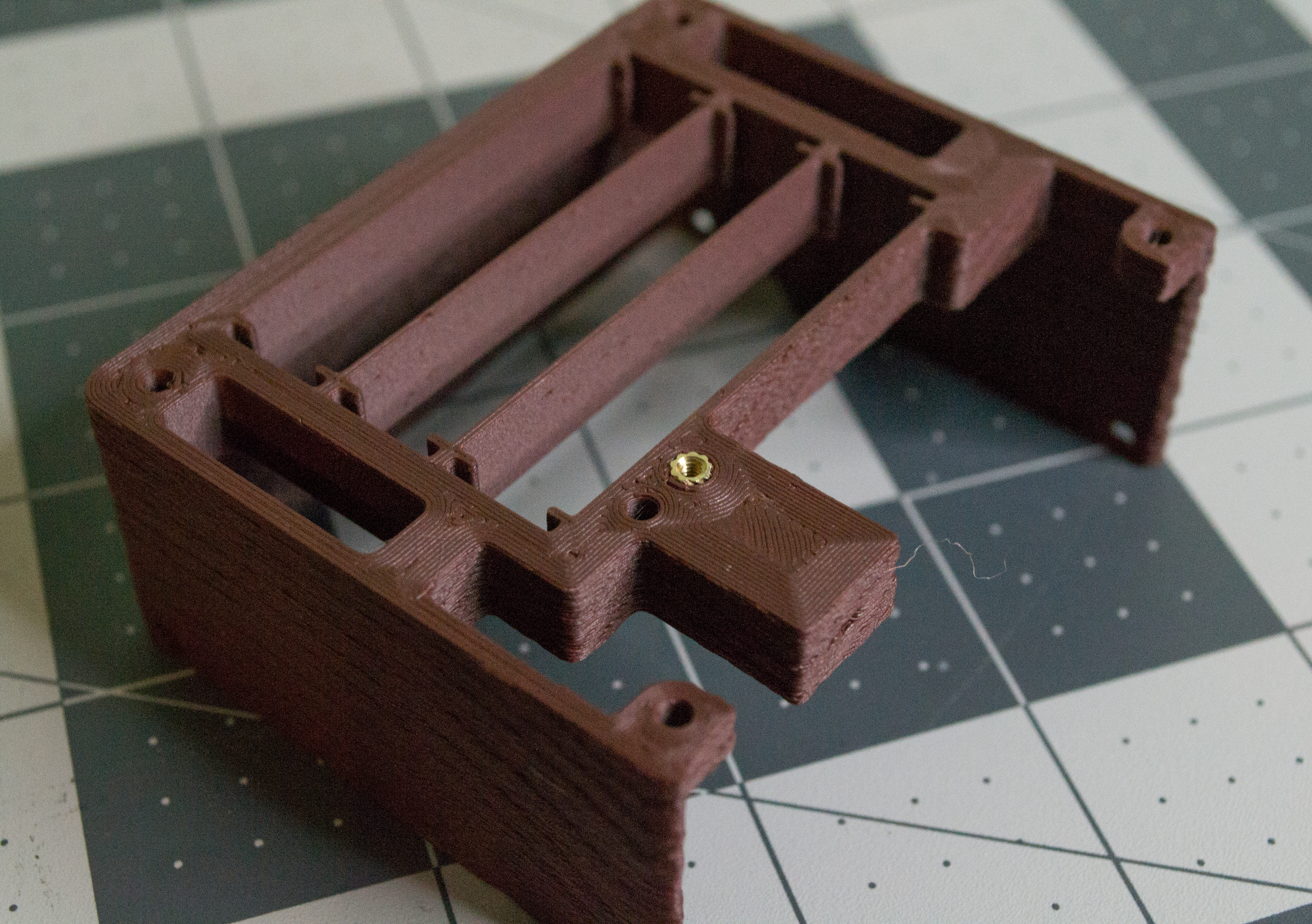
Get the printed Body and the brass threaded insert. The insert goes into the hole used by the M2, 8 mm battery-lid screw. Use a hammer to lightly tap the insert into the plastic. It helps to support the part on a sturdy corner while tapping. A hot soldering iron can also be used, but be careful not to melt the surrounding plastic too much.
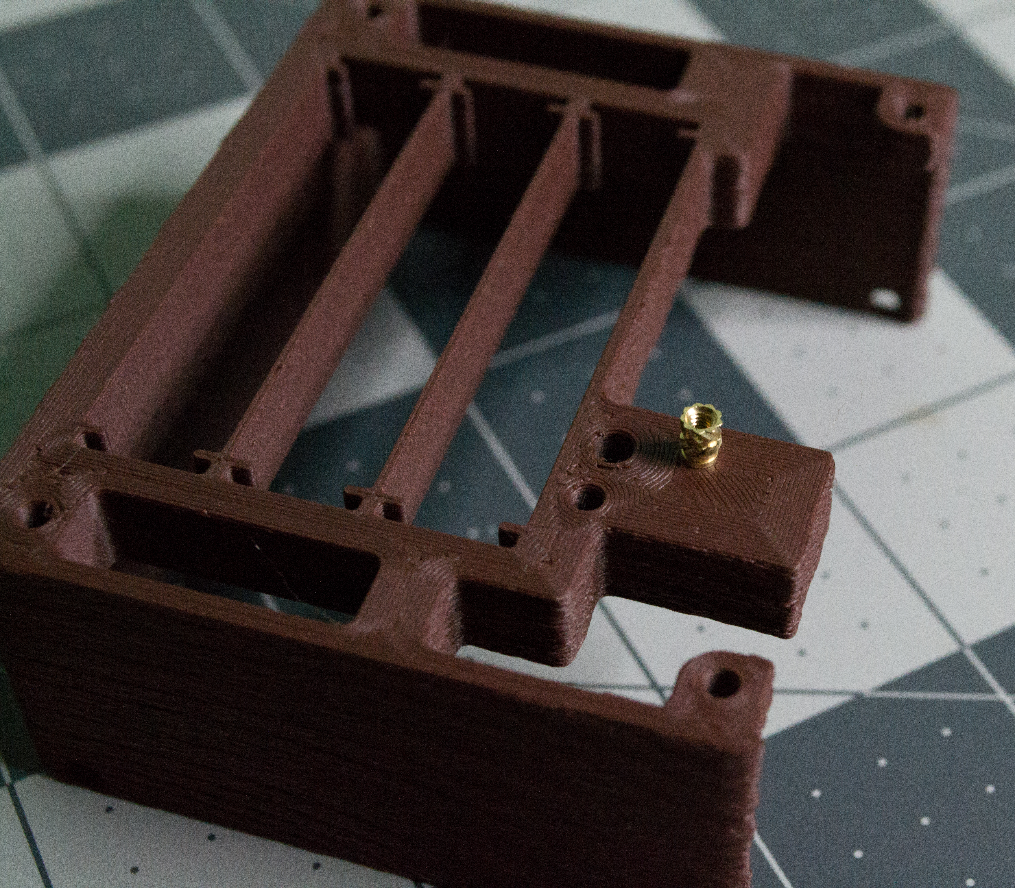 ➜
➜
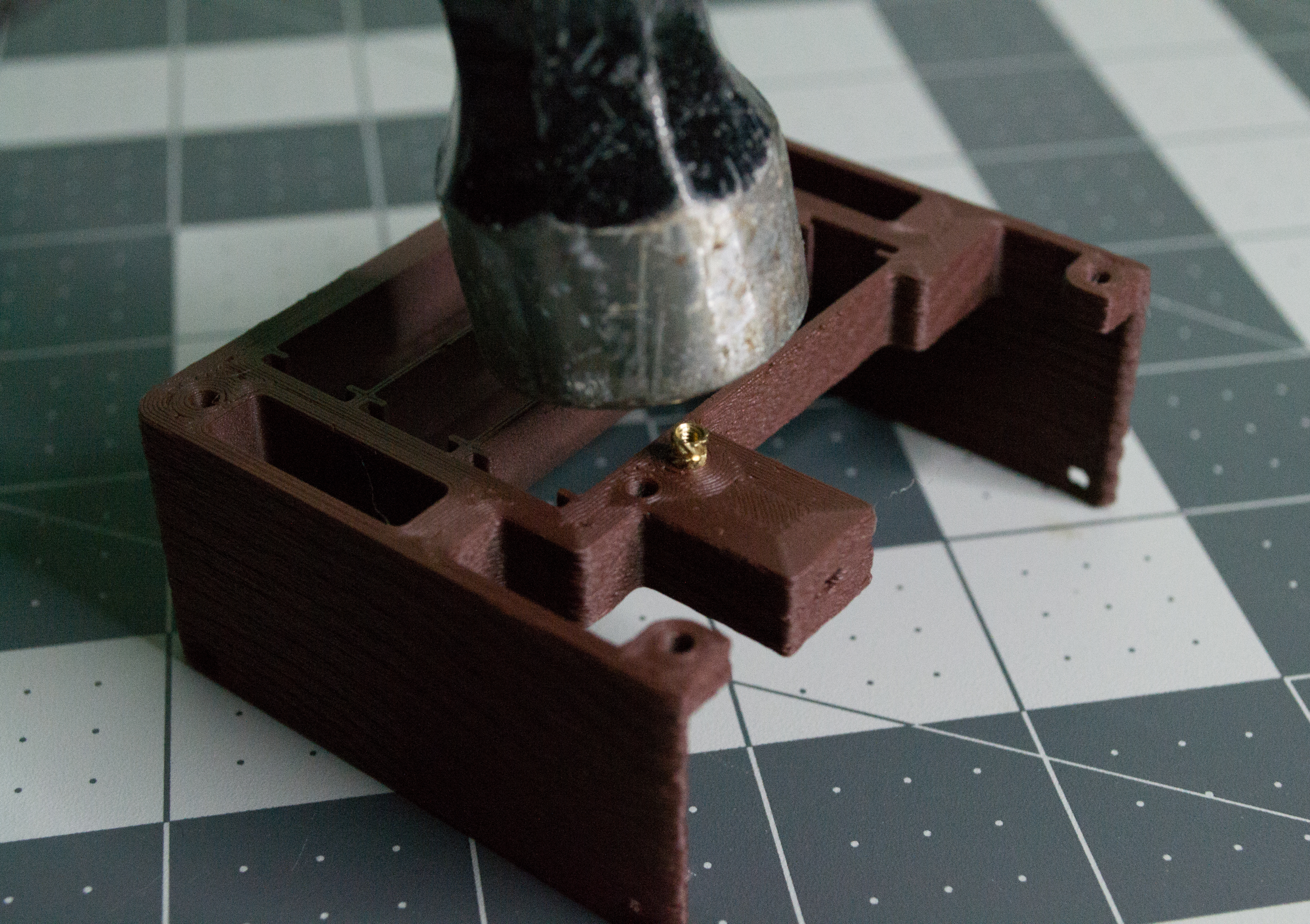 ➜
➜
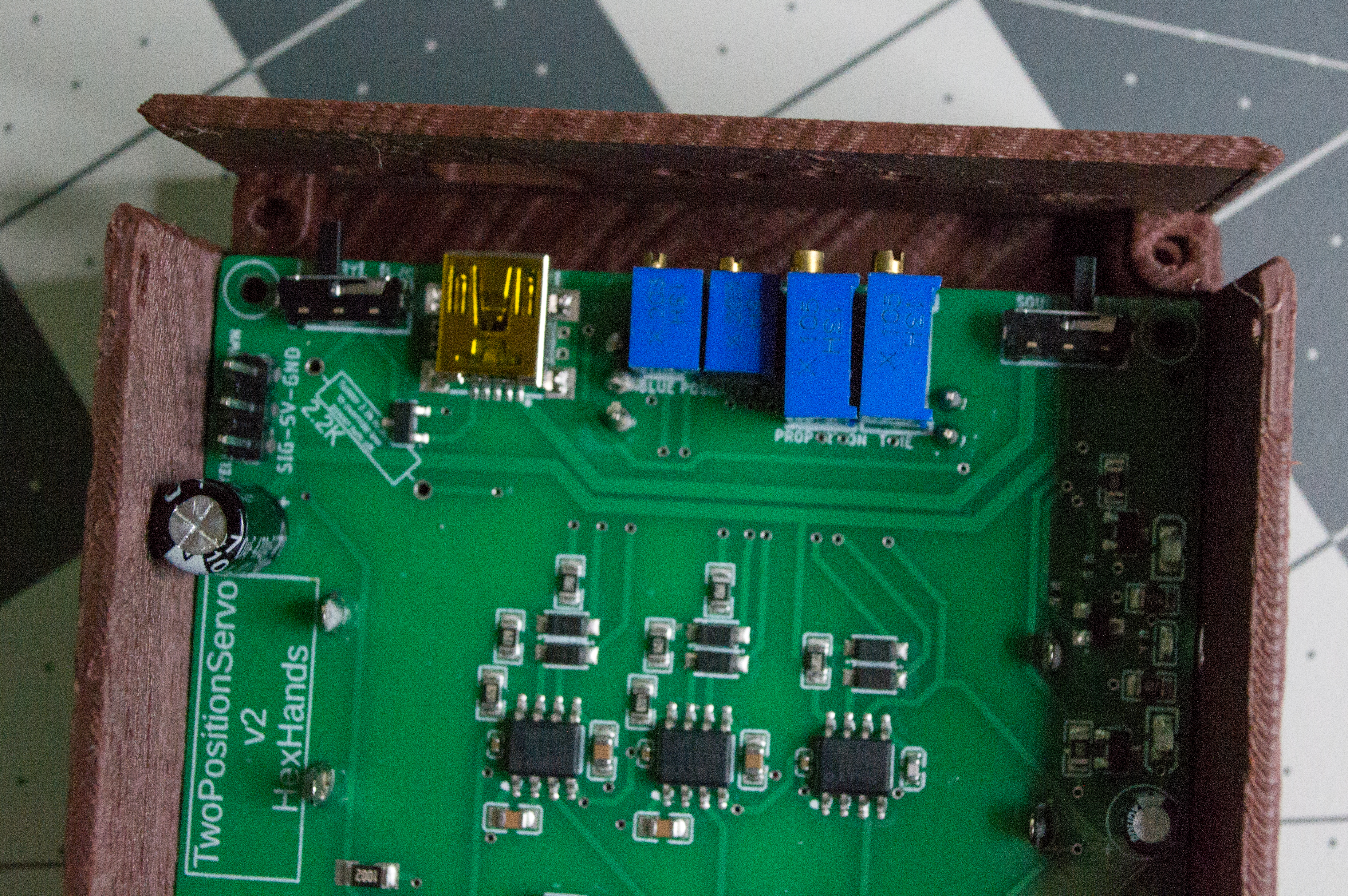
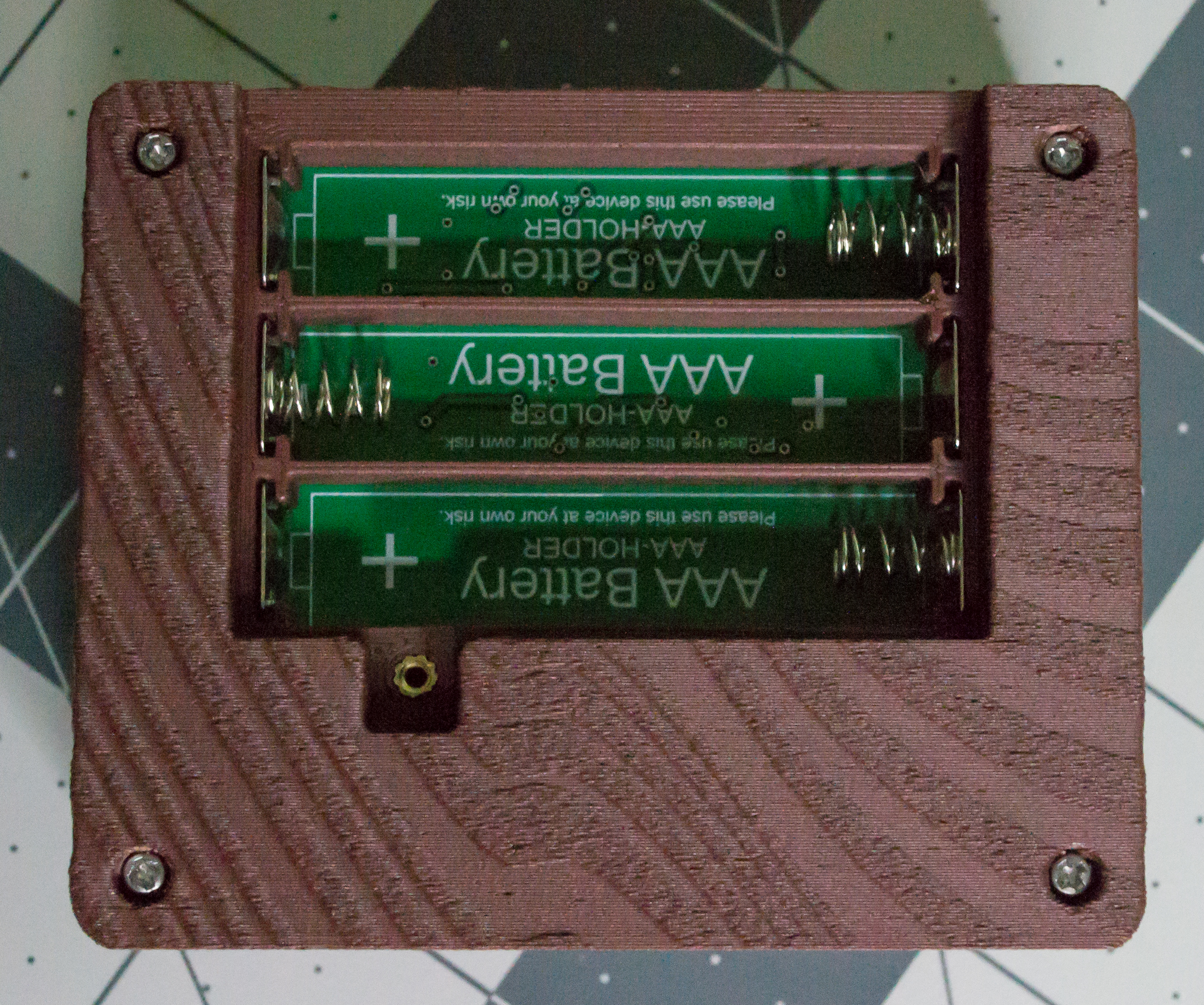
Now insert the assembled TwoPositionServo controller board, making sure the battery contacts drop into the spaces provided in the Body.
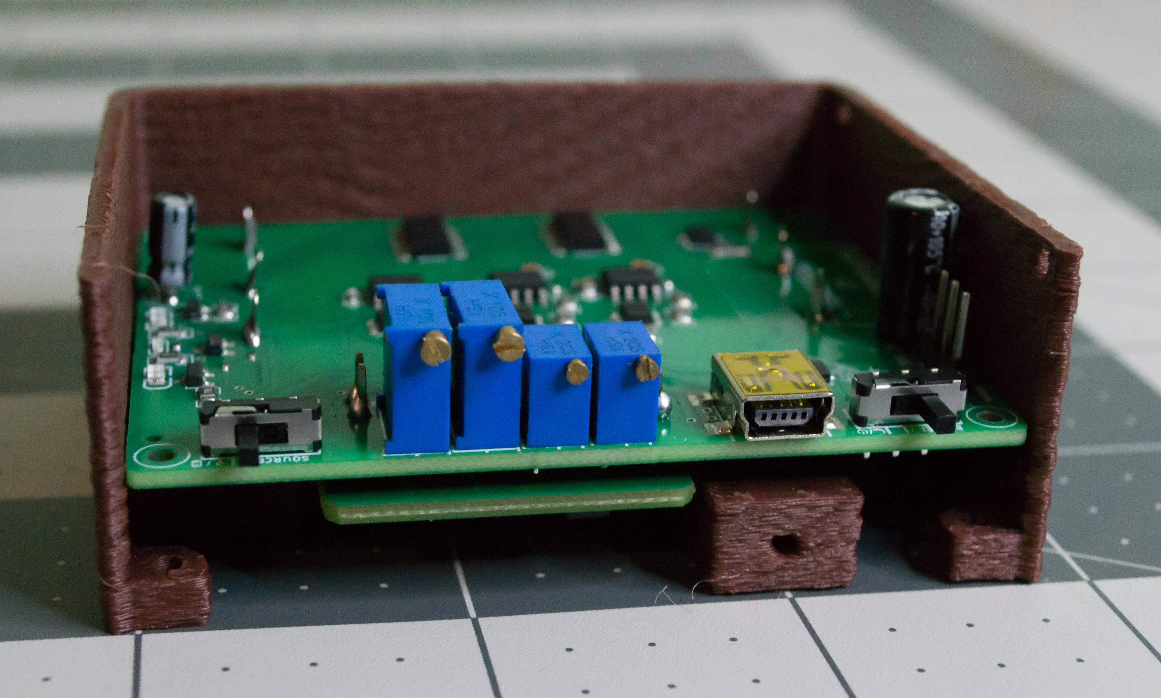
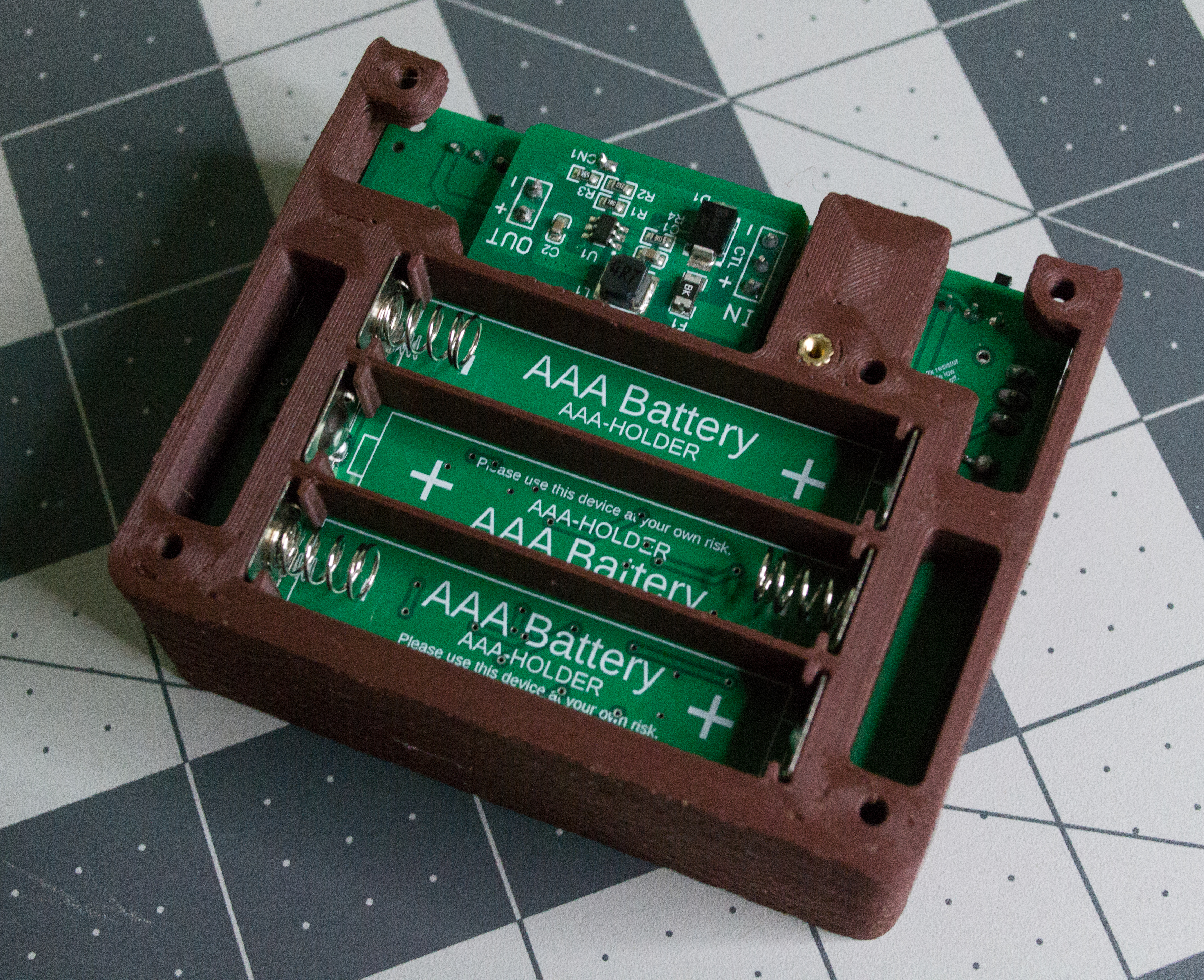
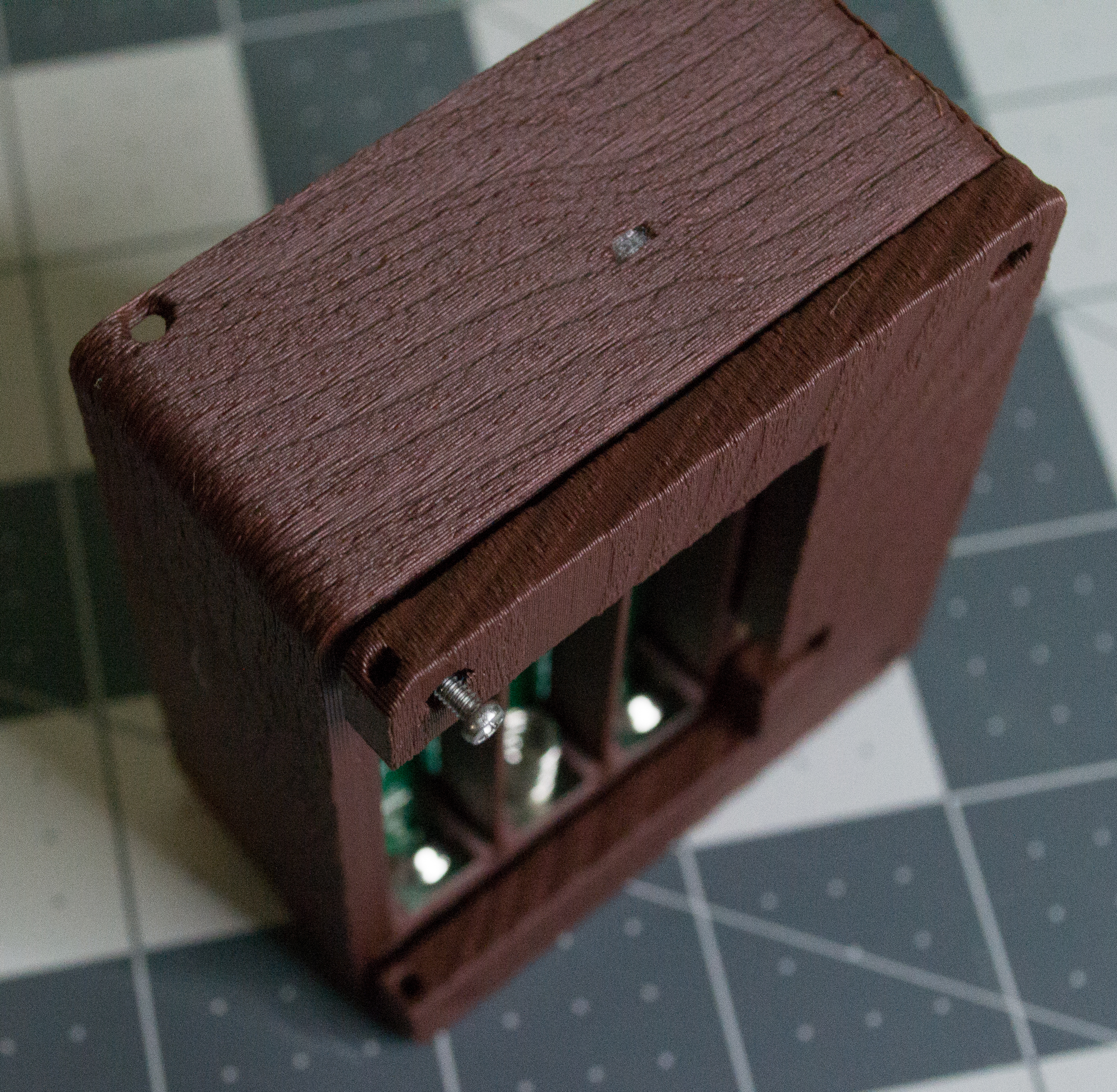
Next, find the printed Bottom and slide it in from the side. Watch the switches as you slide the part in, since they can catch on the edges.
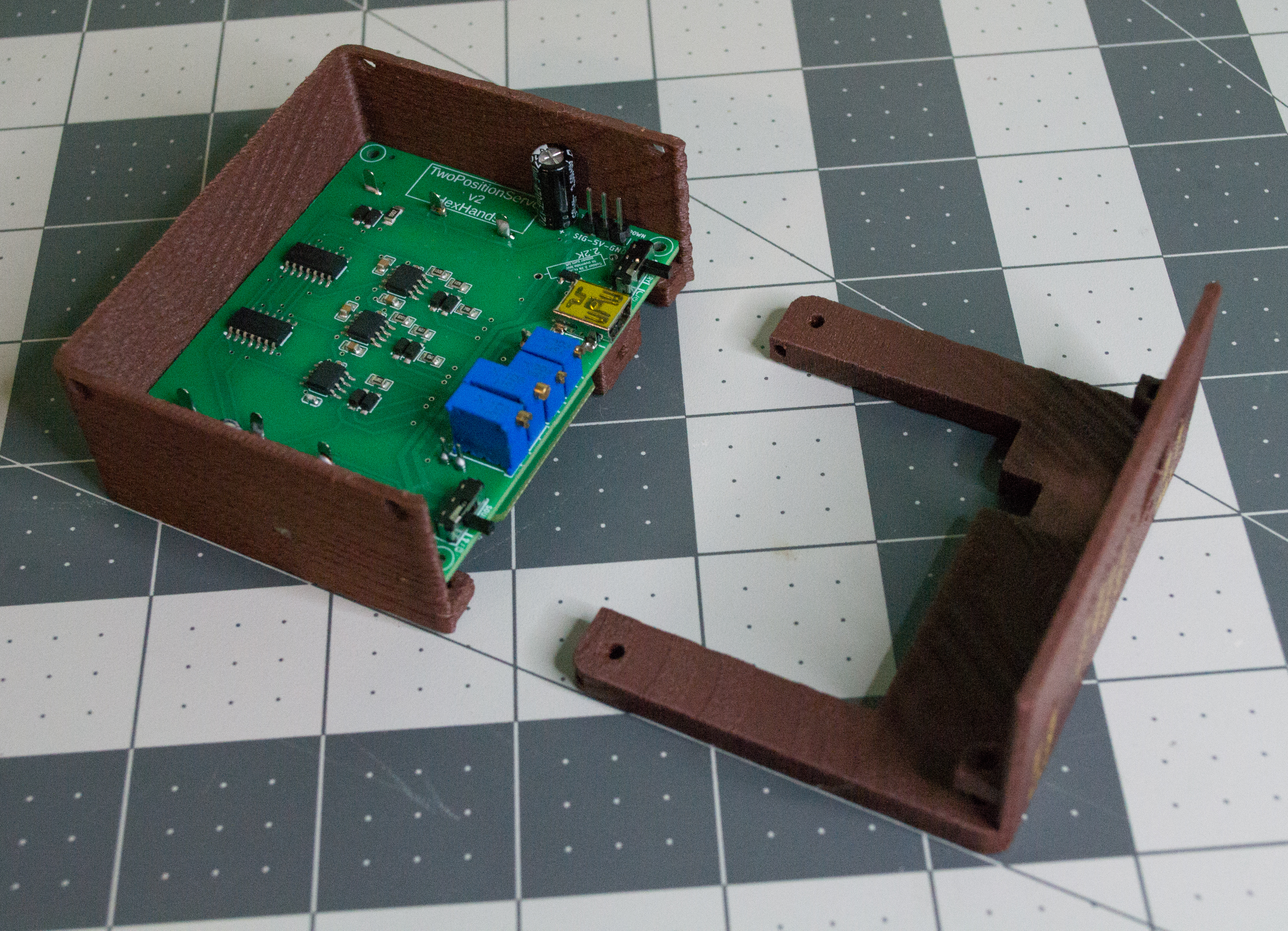
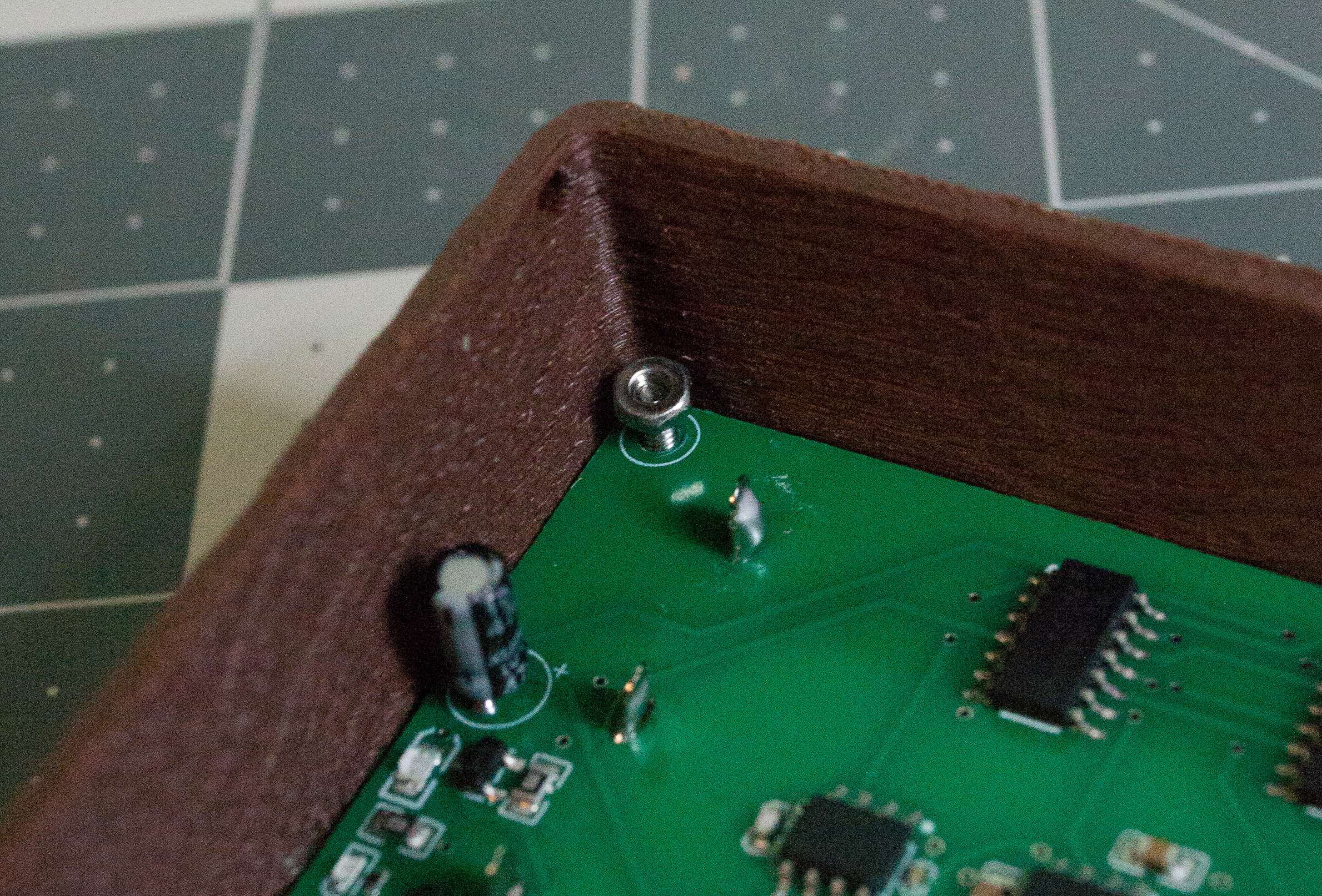
Use four M2, 16 mm machine screws from the bottom of the case to hold the Bottom, Body, and PCBA together. They should slide through, but a small push or a few turns with the screwdriver may help. Once the screws come through on the PCBA side, add one M2 hex nut to each screw and tighten them enough to hold everything in place.
 ➜
➜
 ➜
➜
 ➜
➜
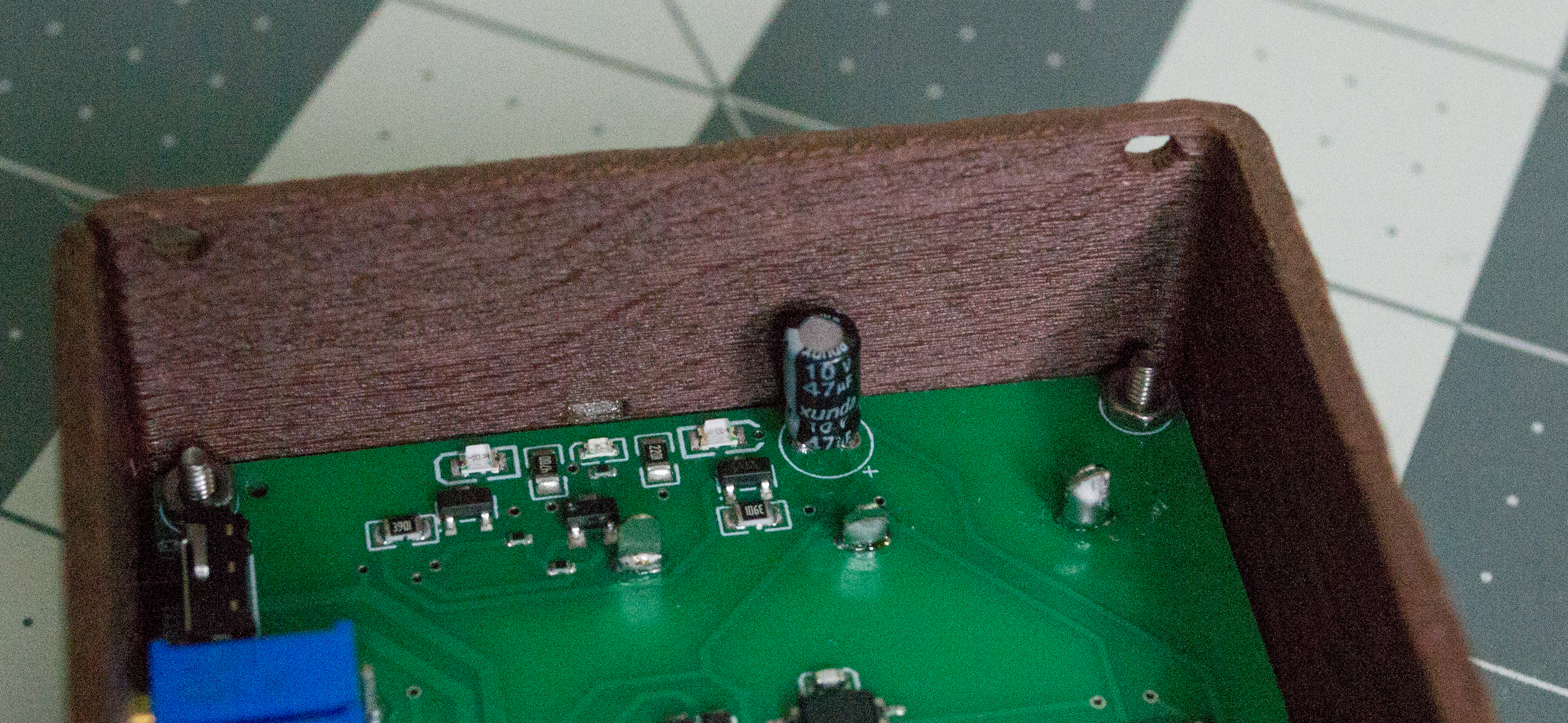
Check: The Body, Bottom, and PCBA should feel secure, the switches should still move freely, and all four M2, 16 mm machine screws should have one M2 hex nut on the PCBA side.
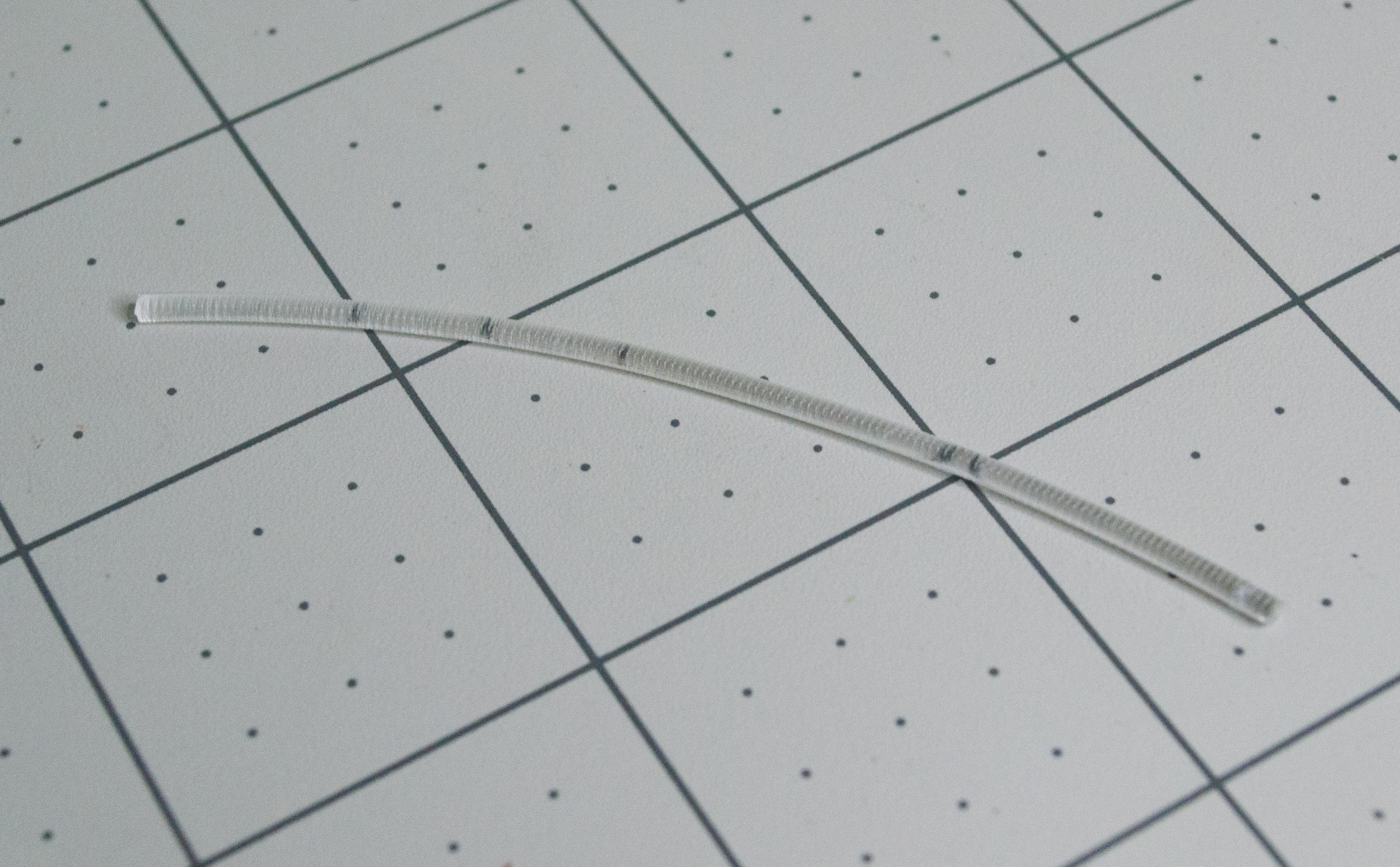
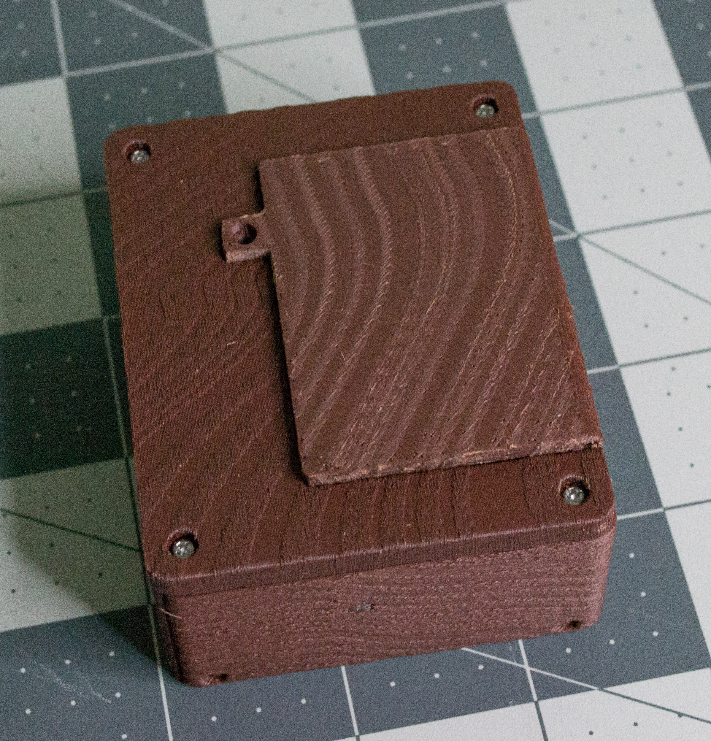
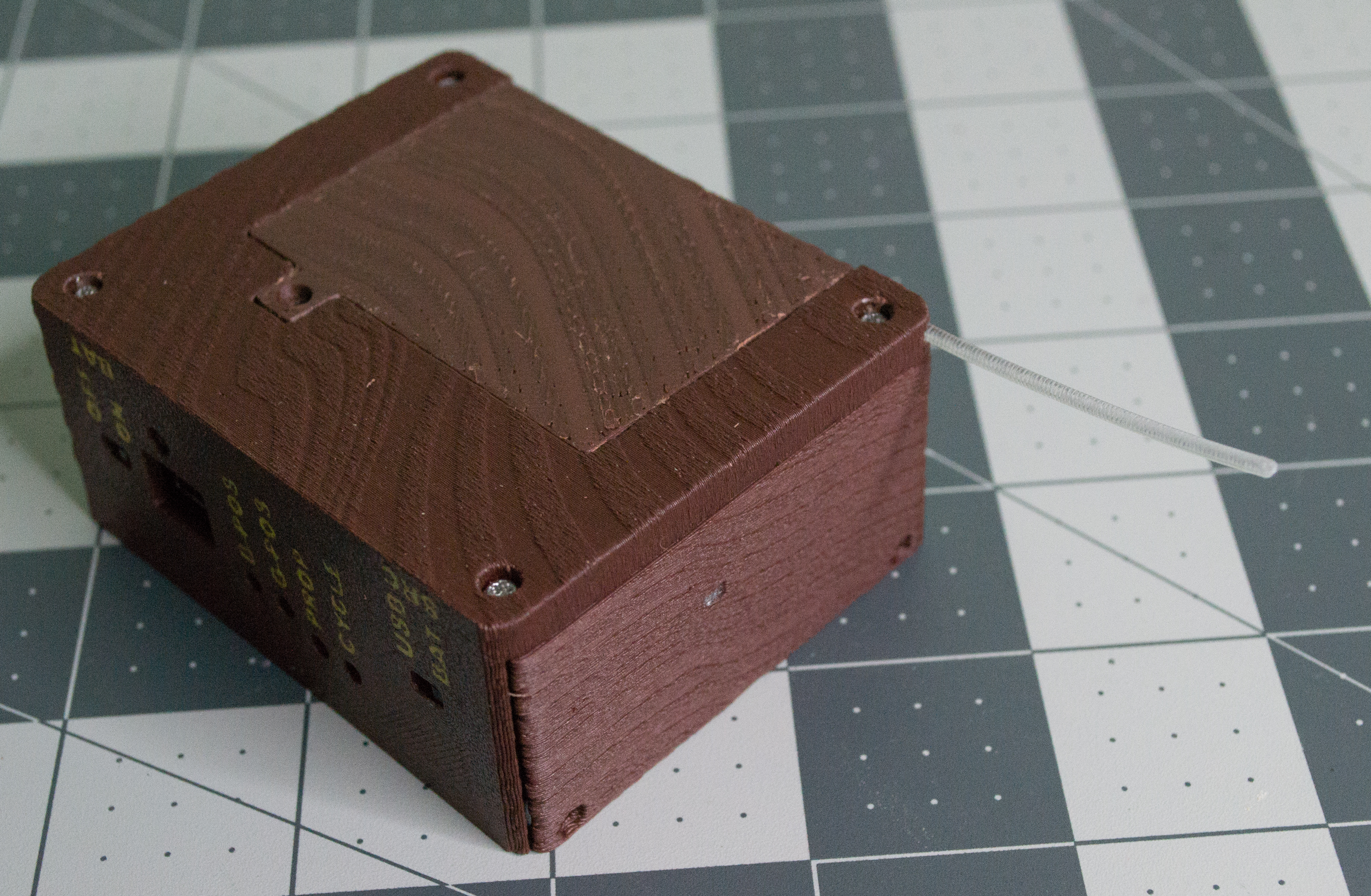
To attach the battery lid, cut an approximately 7.5 cm piece of 1.75 mm filament. I used transparent PETG, but any straight 1.75 mm filament piece should work. Place the Lid into position. Depending on your print settings and wood-grain texture, you may need to lightly sand the edges. If the hinge hole is too tight, carefully open it with a 2 mm drill bit. Push the filament through the hinge hole so only a small amount extends beyond the body. This creates the filament hinge. Optionally, you can slightly melt the ends with a soldering iron so the hinge pin stays in place.
 ➜
➜
 ➜
➜
 ➜
➜
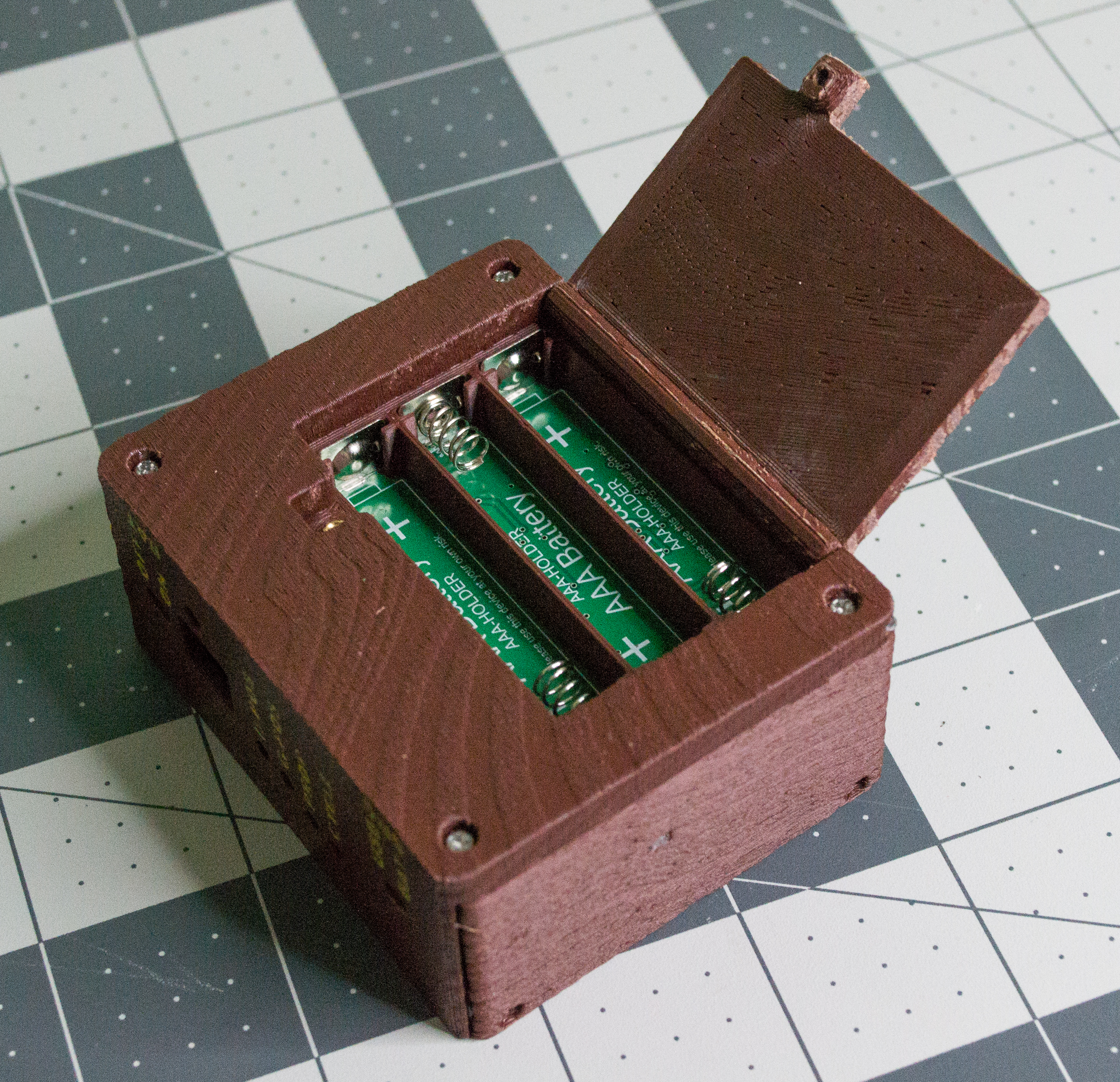
Add one M2, 8 mm machine screw into the brass threaded insert to hold the battery lid closed. The battery compartment is now complete.
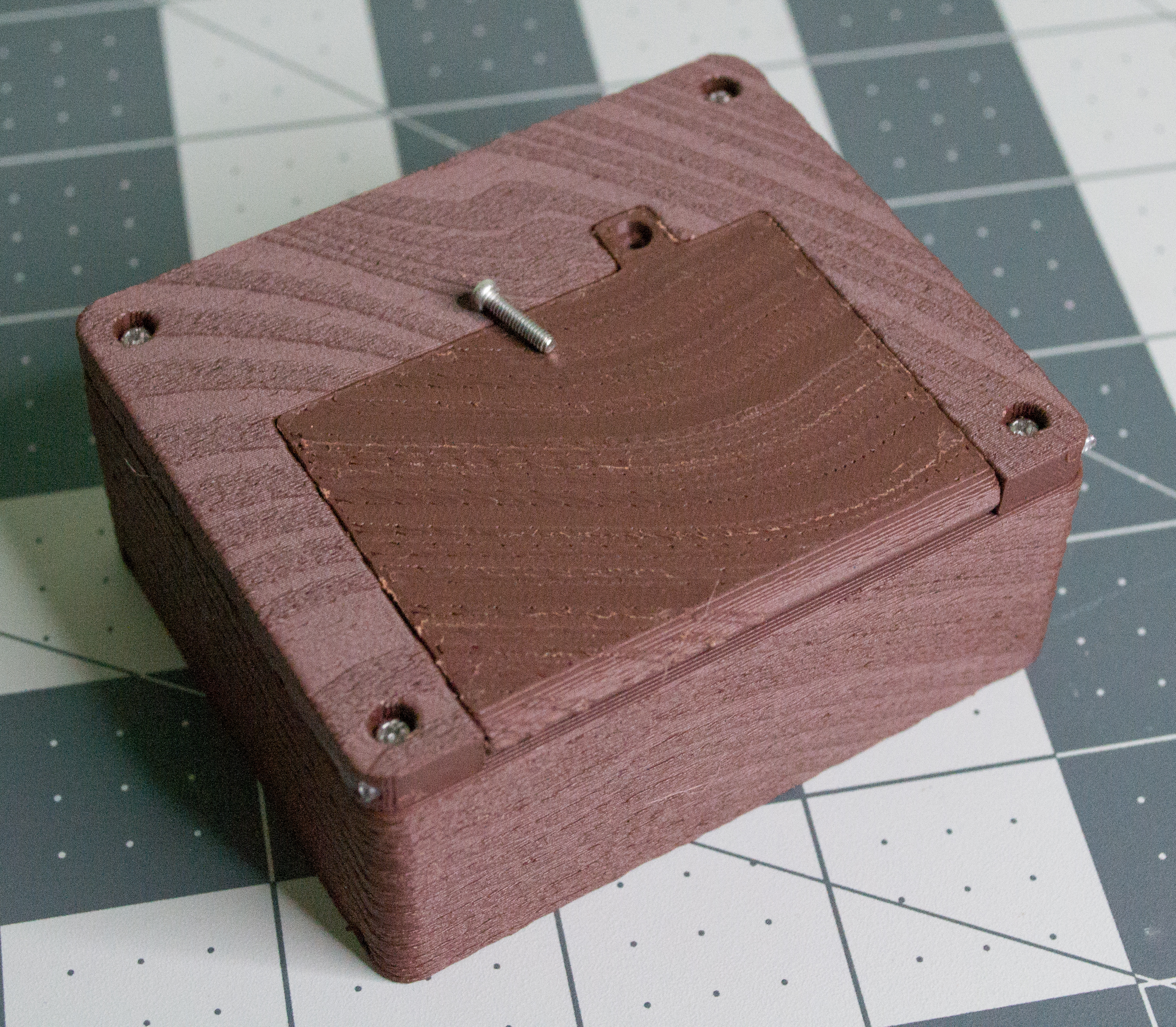
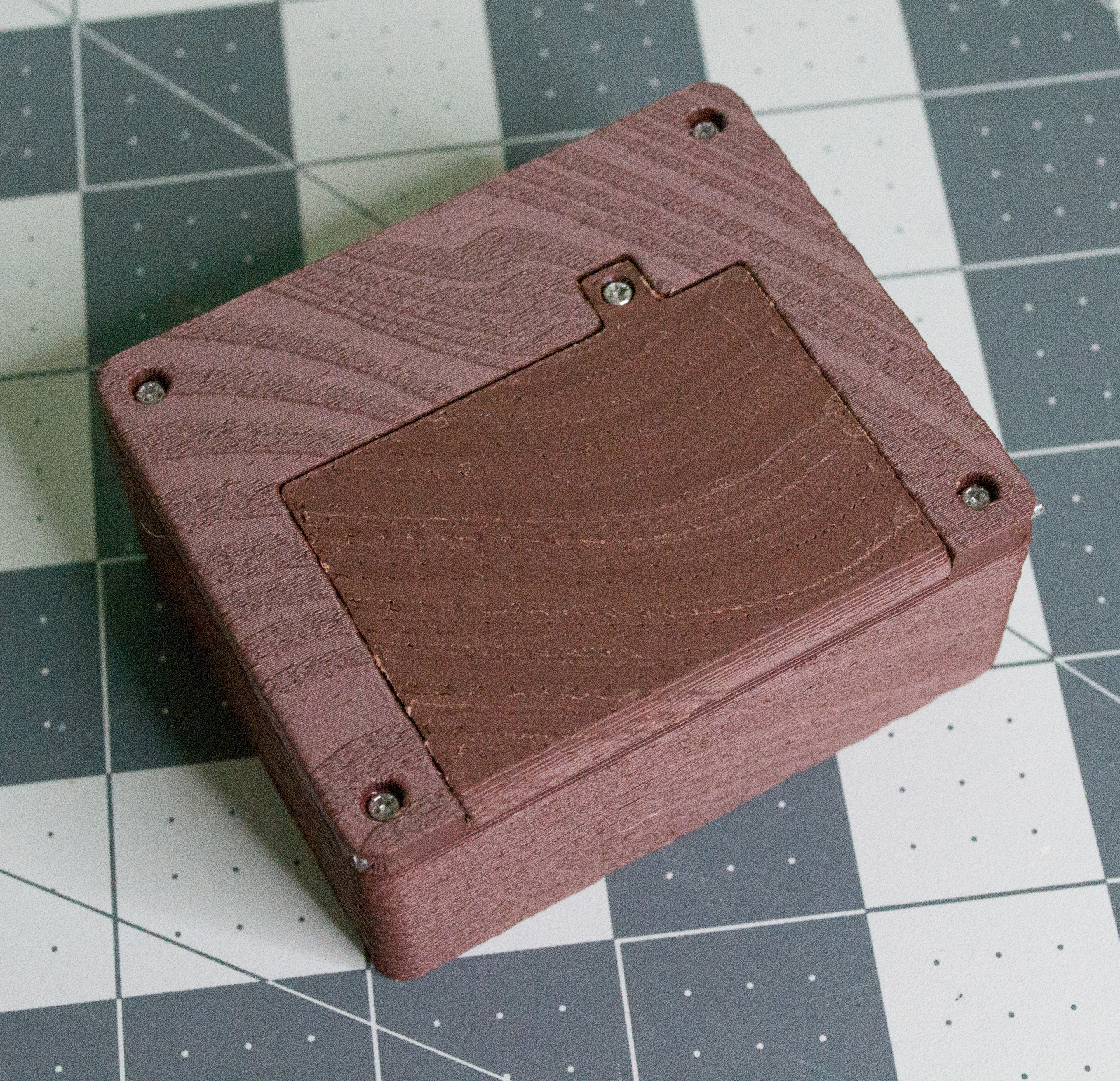
Check: The printed Lid should open and close smoothly, and the M2, 8 mm machine screw should thread into the brass threaded insert without forcing it.
Servo Arm and Linkage
Next, move to the top assembly. Find the printed Arm and some monofilament. The Arm will attach to the servo and move the Lever through the monofilament linkage. Cut two long strands of clear monofilament line, each long enough to travel from the servo arm, up through the mast, and through the Lever. Extra length is helpful because it can be trimmed later.
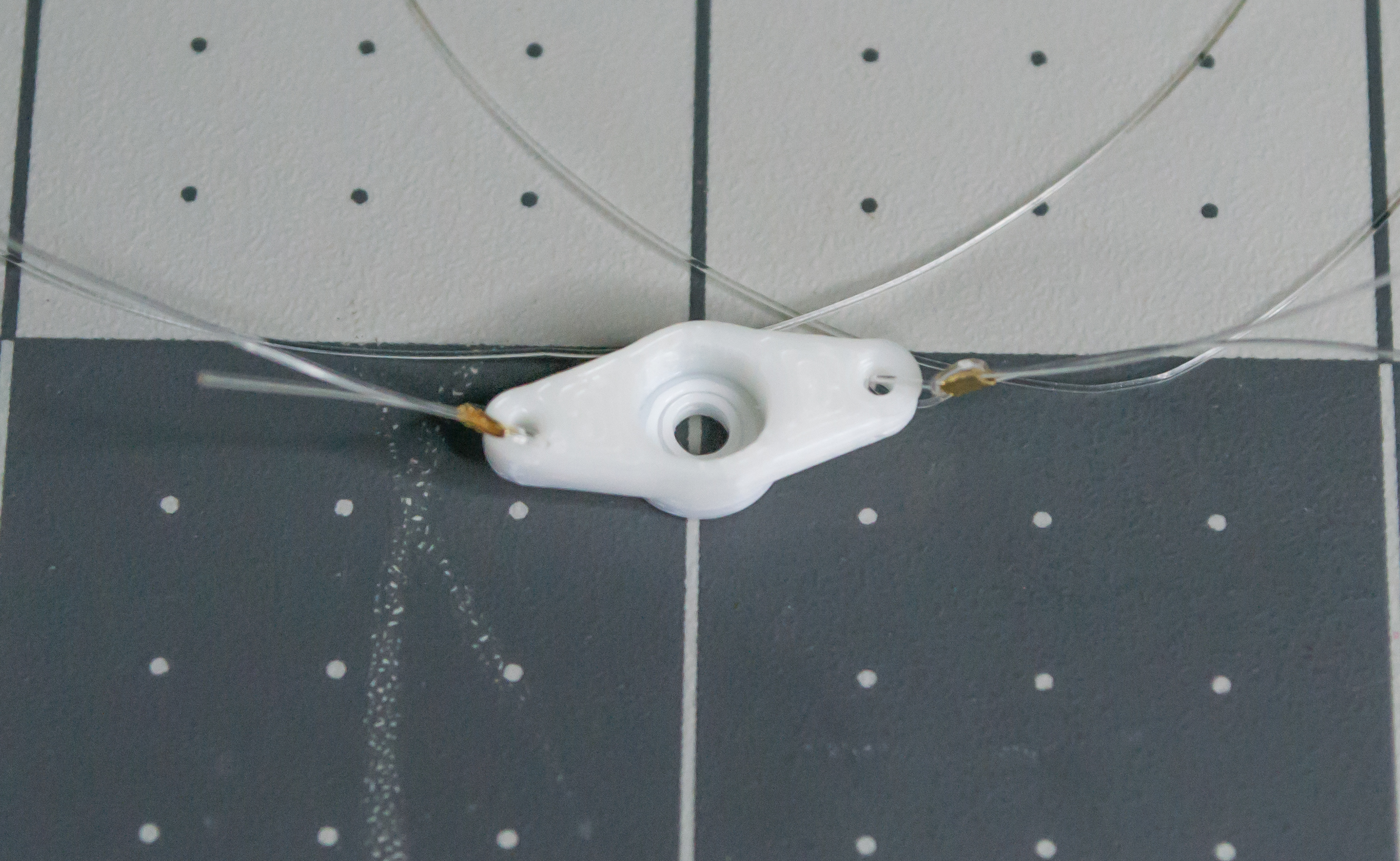
In the images below, one side of the Arm is already completed. Repeat the same steps on the other side so monofilament is attached to both holes in the Arm.
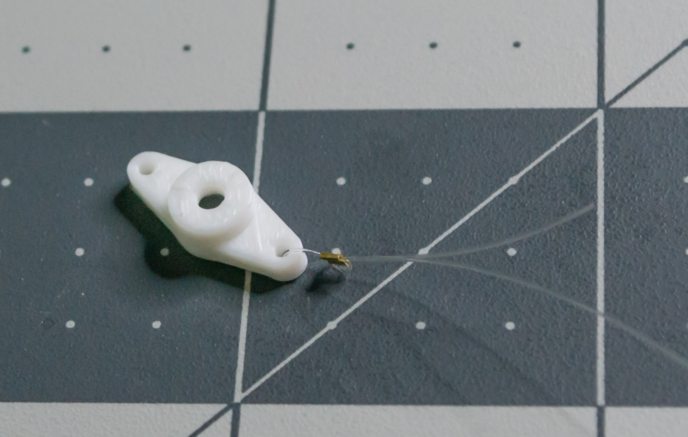
First, feed one piece of monofilament through one of the side holes in the Arm. The direction does not matter.
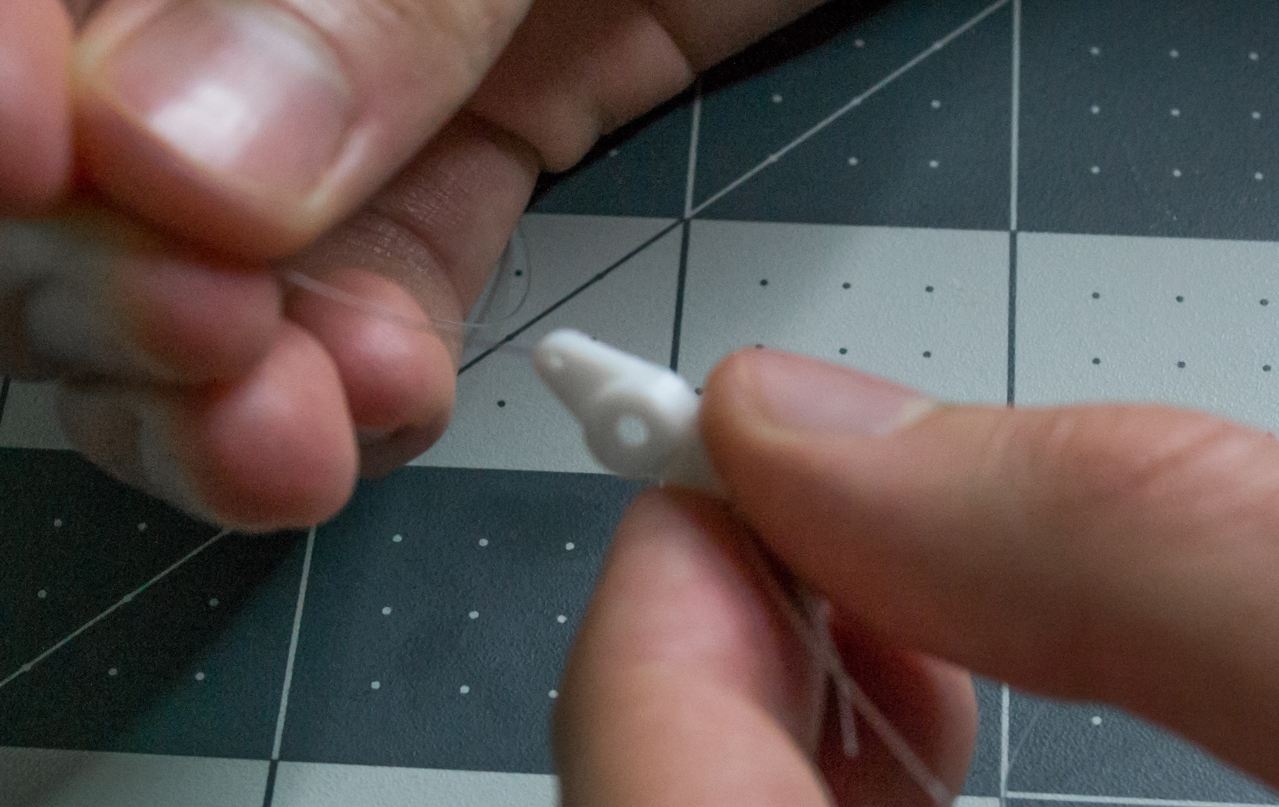
Next, take one small gold crimp bead and pass both ends of the monofilament through it. Take the short end and wrap it back through again to create a second loop. This helps stop the line from slipping after it is crimped.
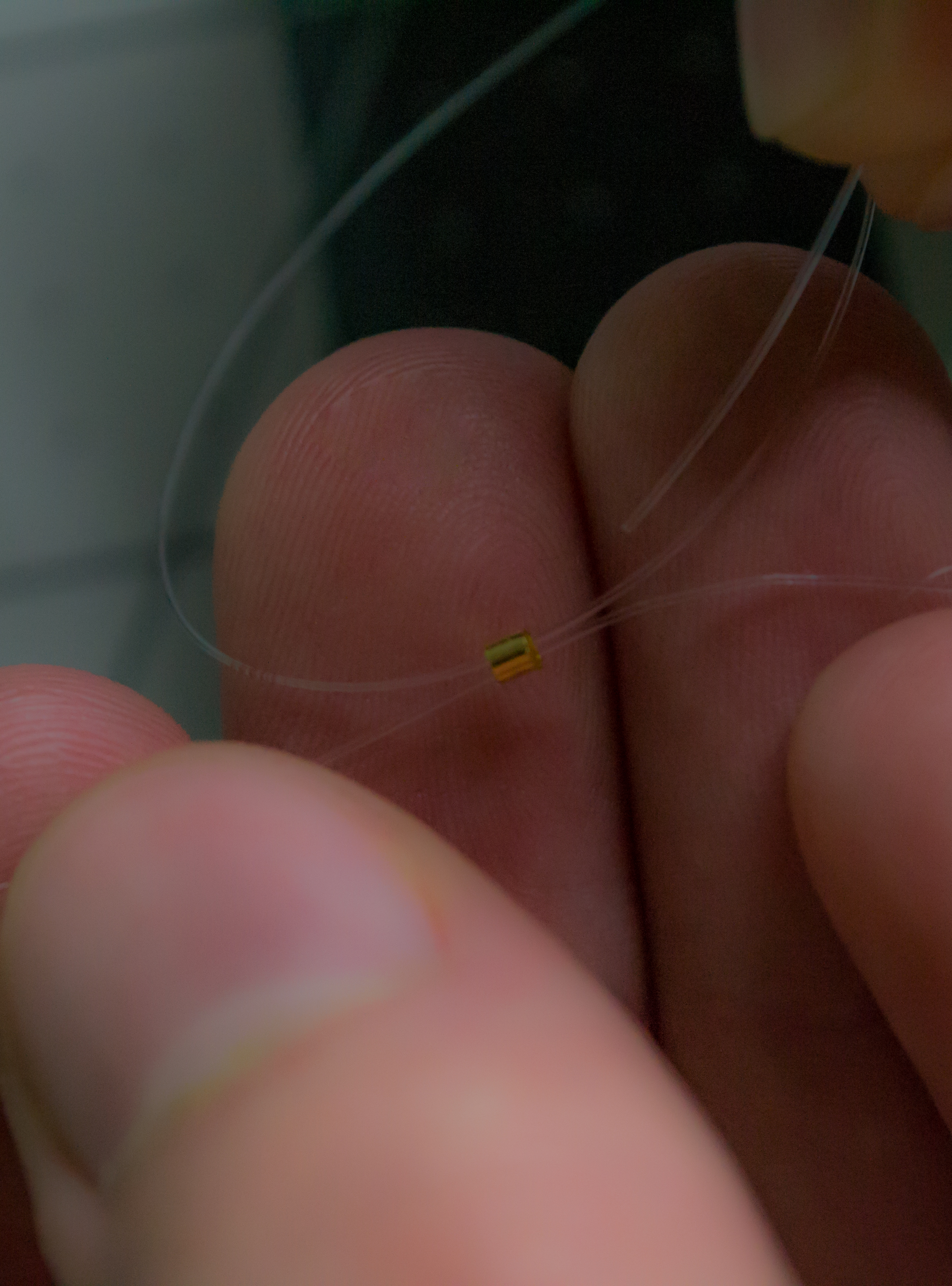
The result before crimping should look like this. The uncrimped bead is the top one.
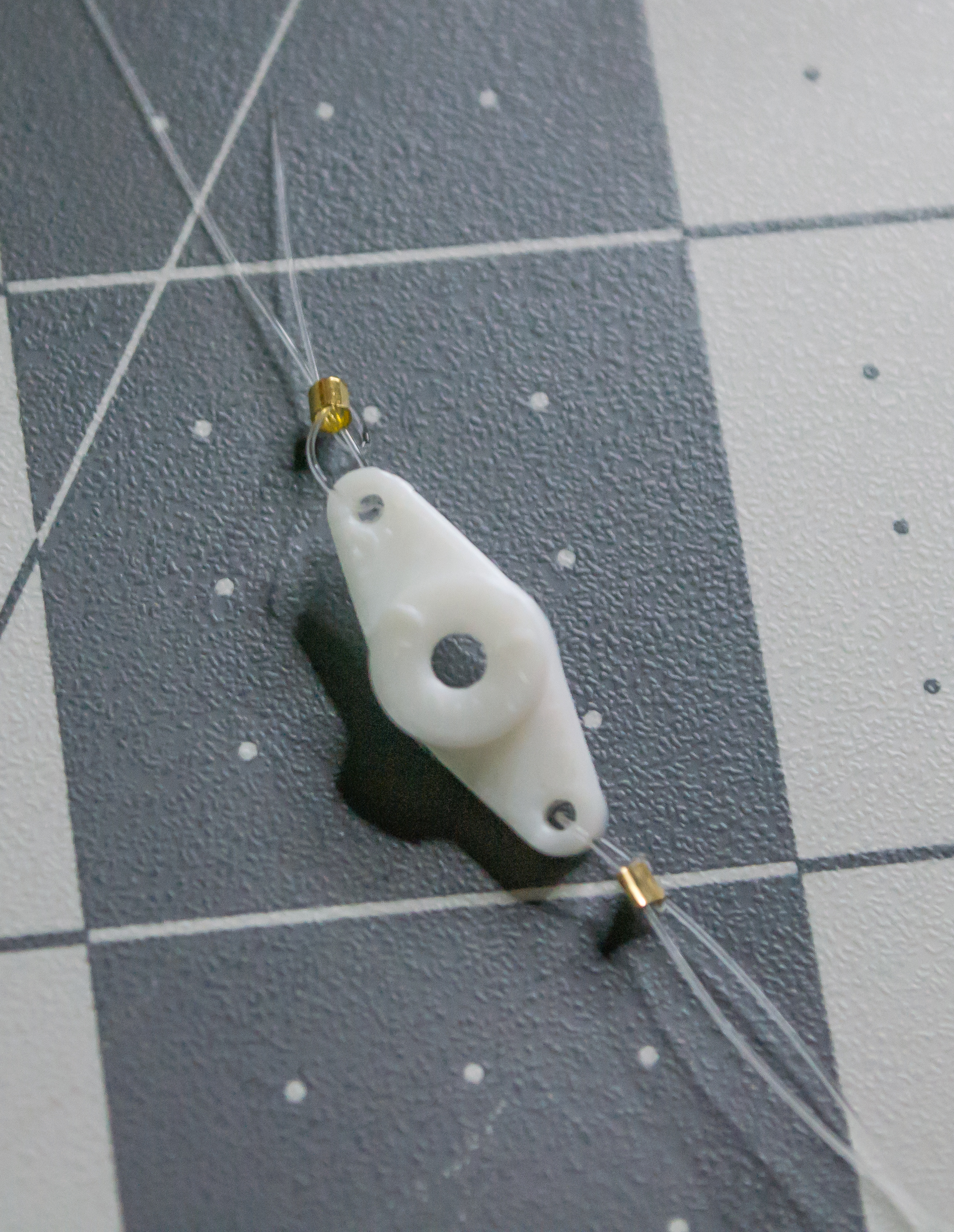
After crimping that bead and doing both sides, the result should look like this.
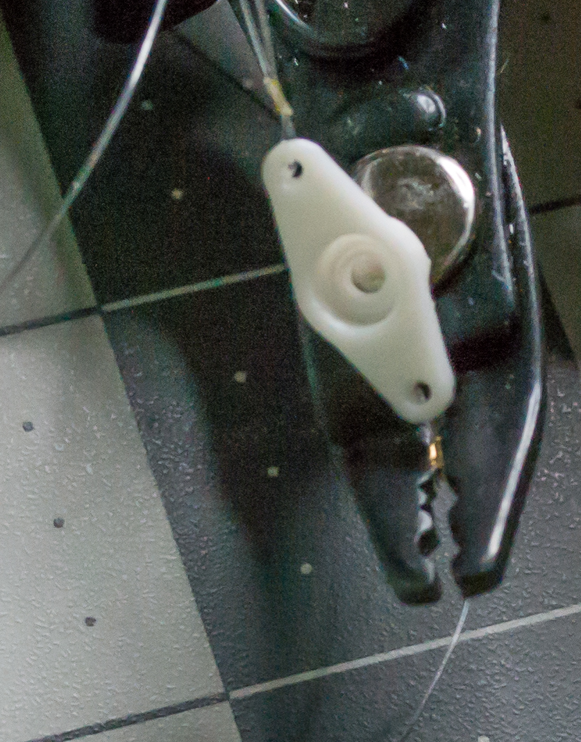
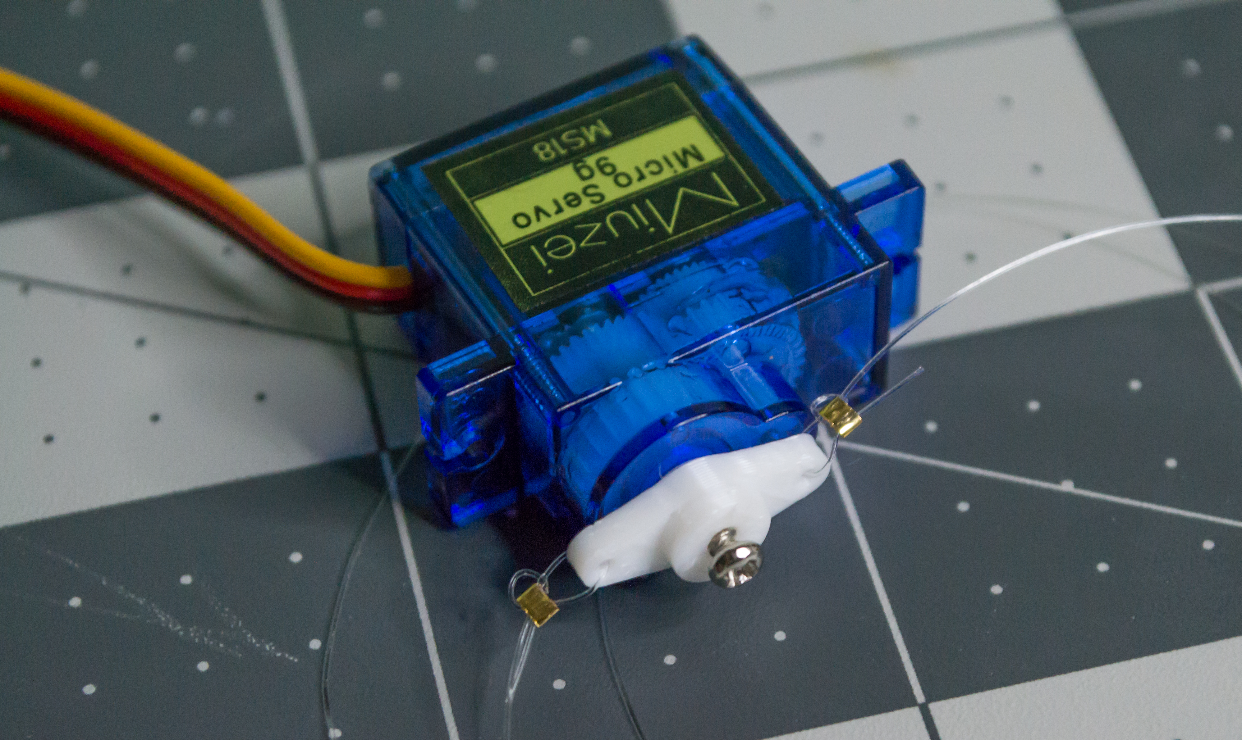
Set up the servo so the Arm starts centered. You may not need the full range of motion, but centering the Arm gives the servo room to move in both directions. The video below shows how I centered it. Be careful when rotating the servo by hand, since forcing it can damage the gears. The printed Arm is mainly meant to be driven by the servo, not used as a handle, so it can slip if you twist it by hand. If needed, you can glue the Arm onto the servo shaft before installing the servo screw.
After the Arm is correctly positioned on the servo shaft, install the servo horn screw to hold it in place.
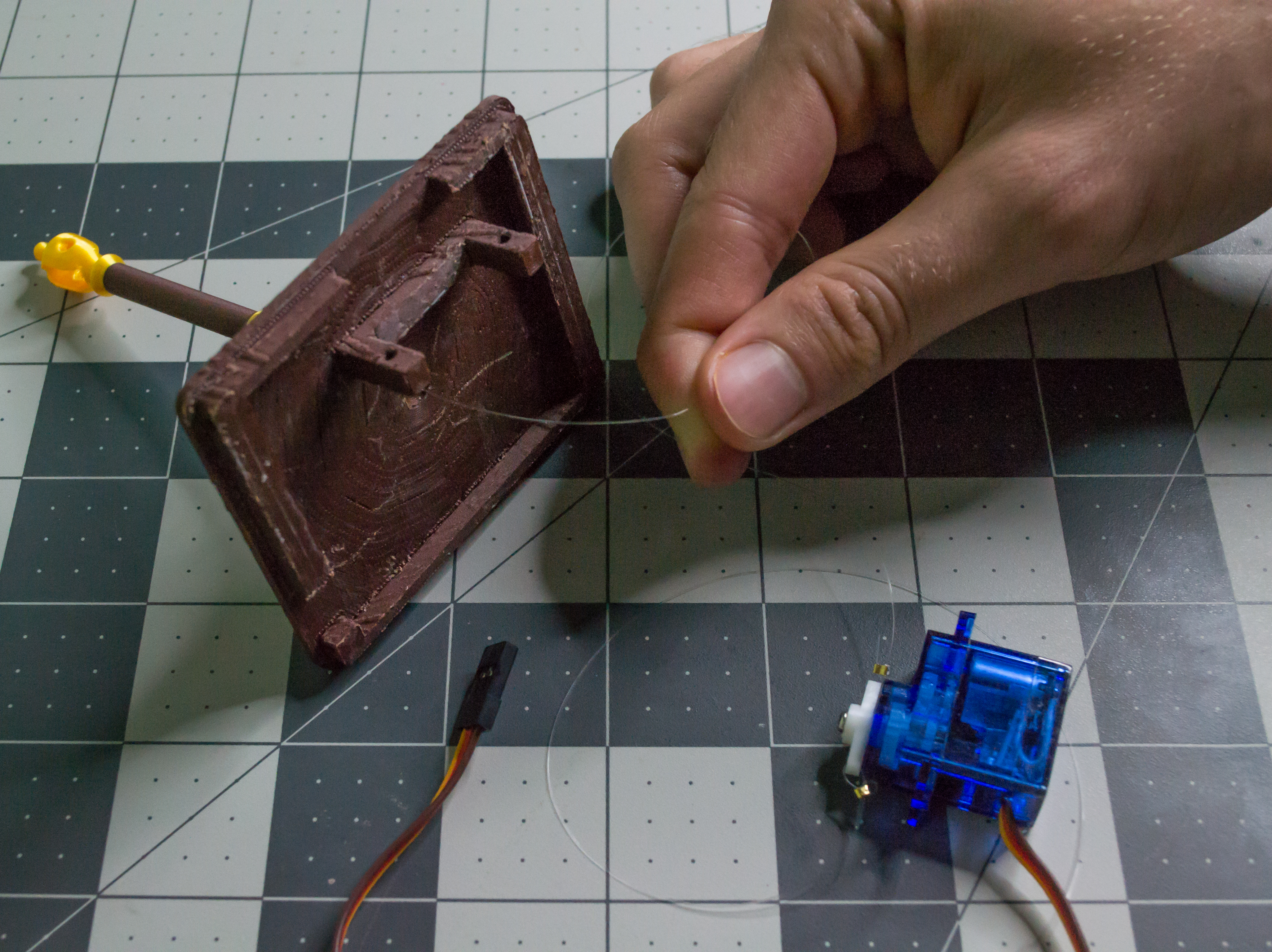
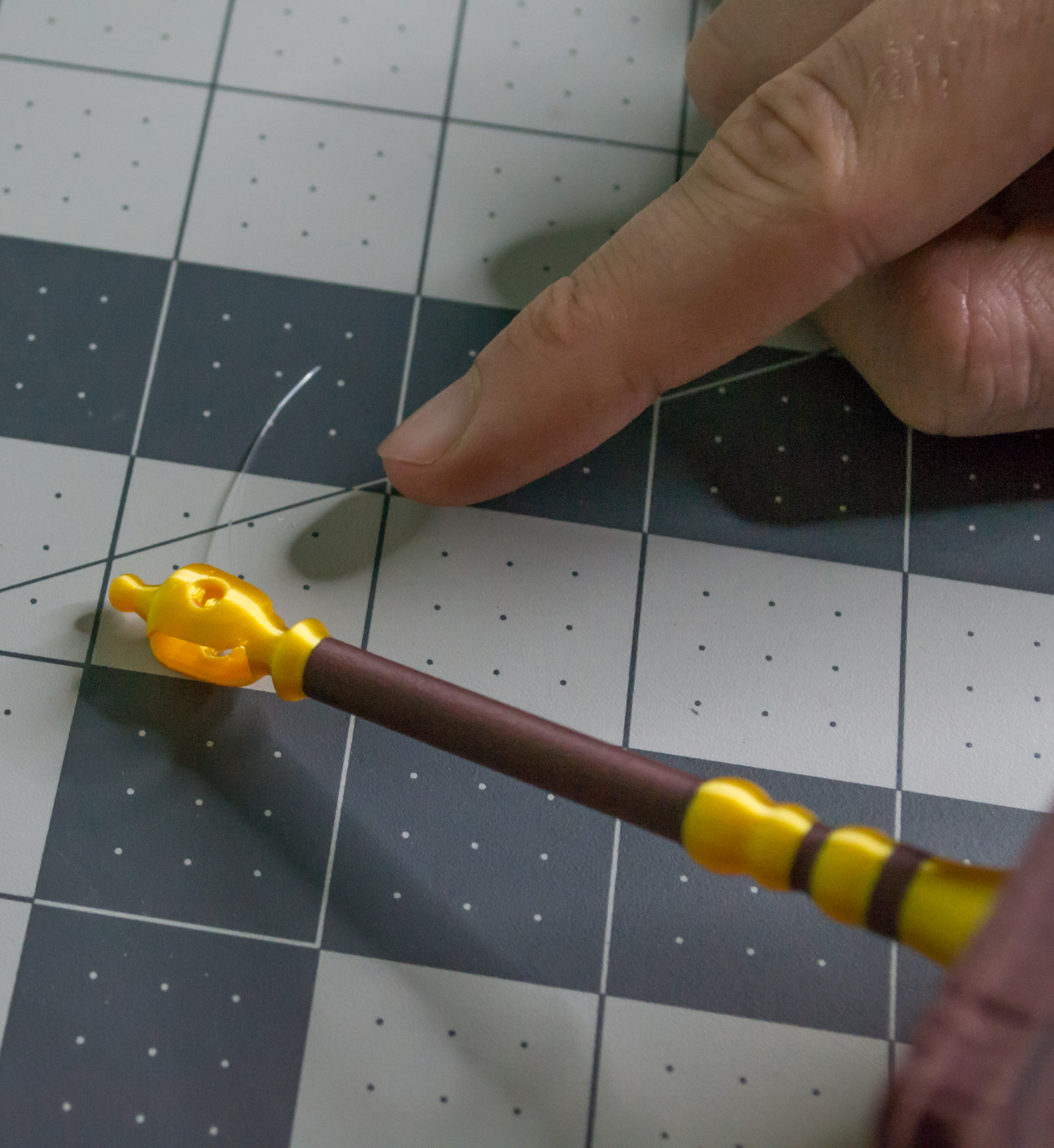
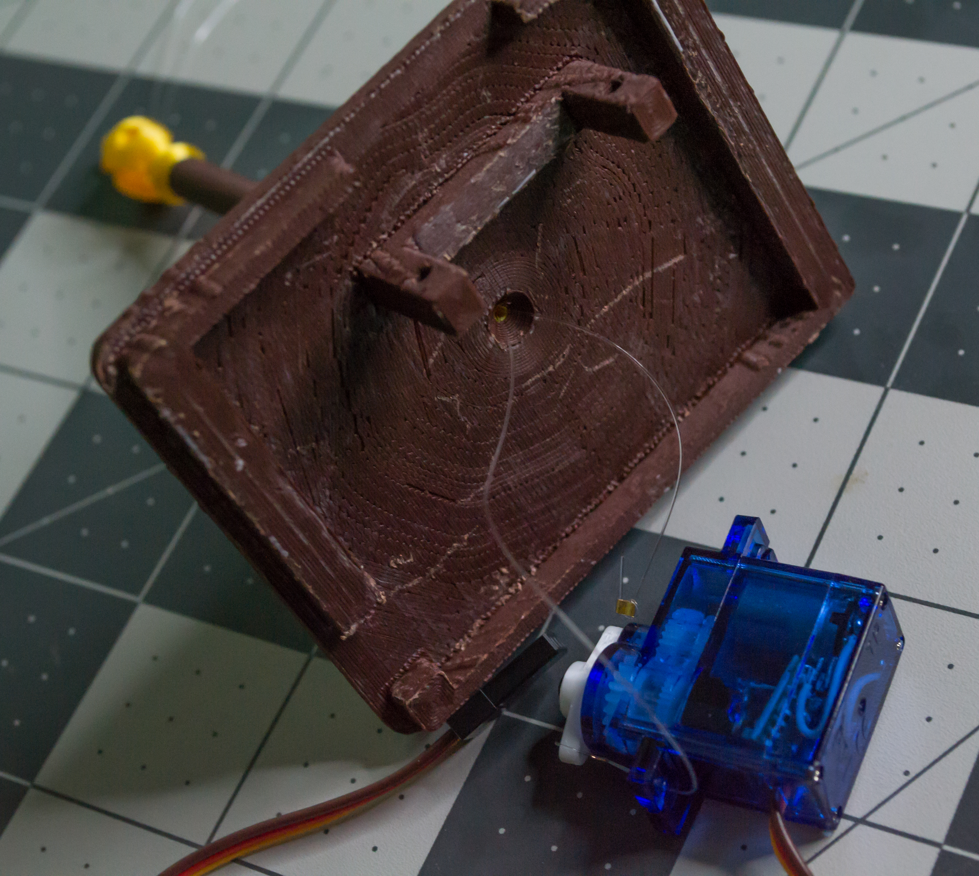
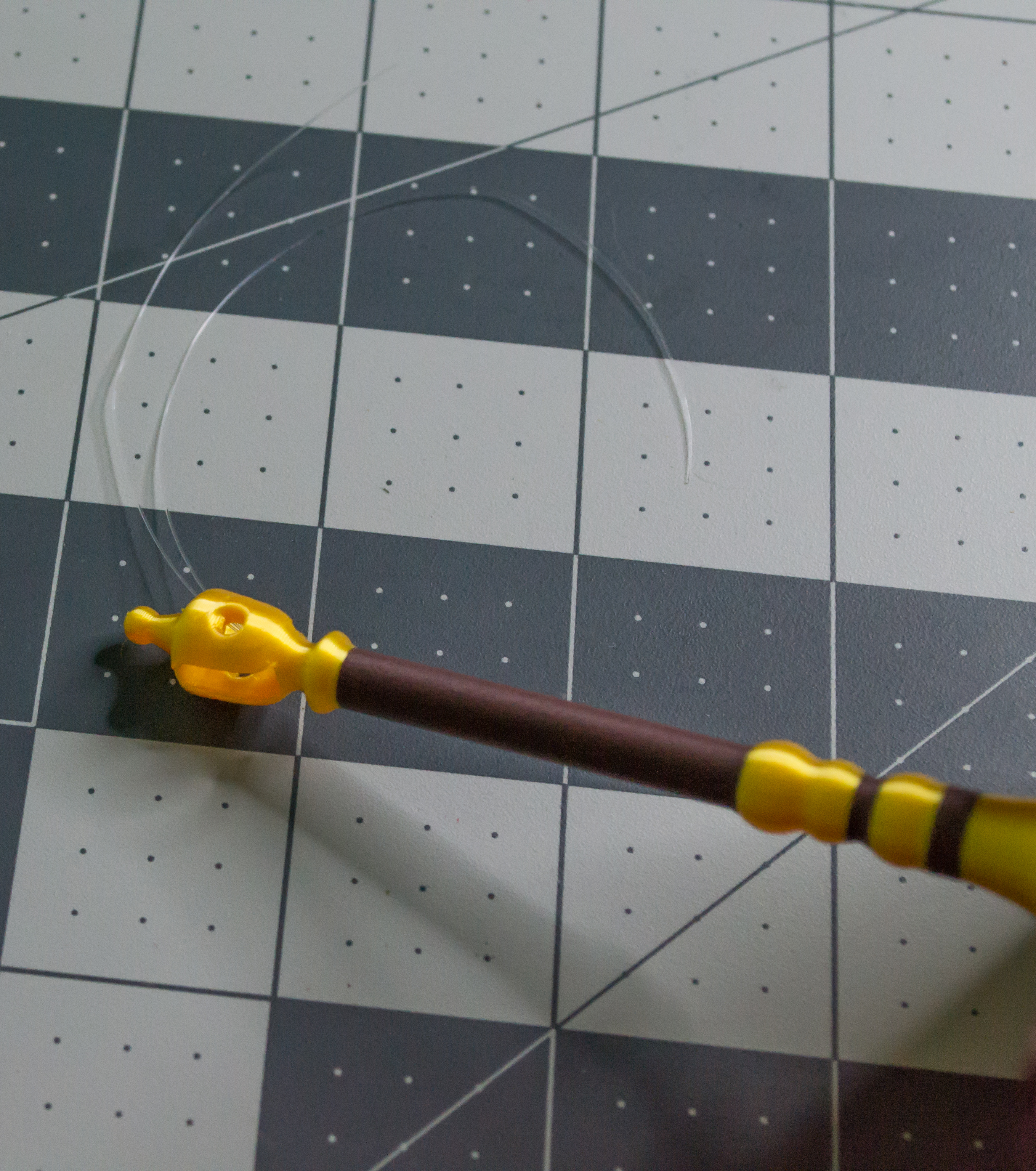
Feed both monofilament lines through the small hole in the Top/Scale component. The hole runs up through the mast. You do not need to keep the two lines separated, because either line can be used on either side of the Lever later. Make sure both lines exit at the top.
 ➜
➜
 ➜
➜
 ➜
➜
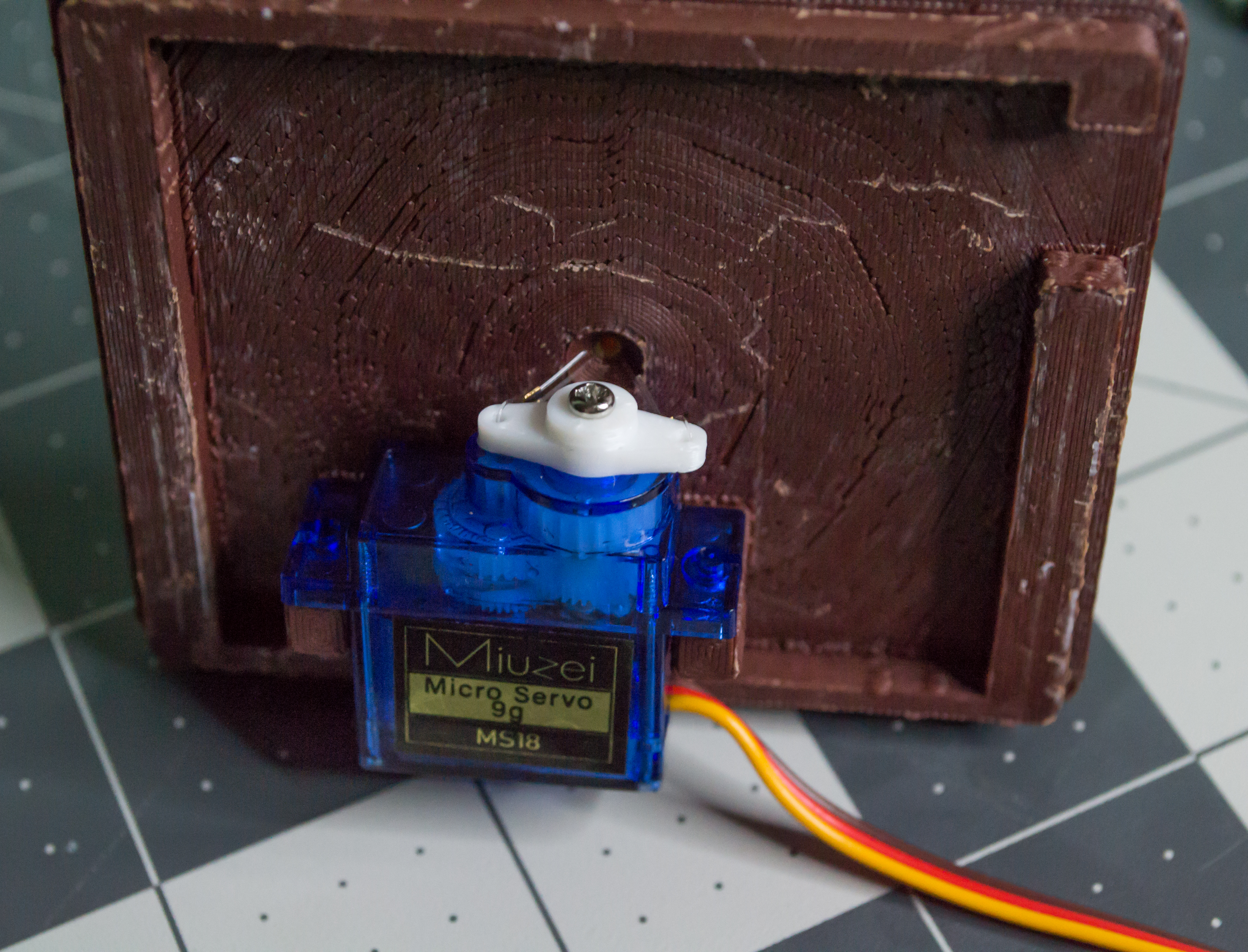
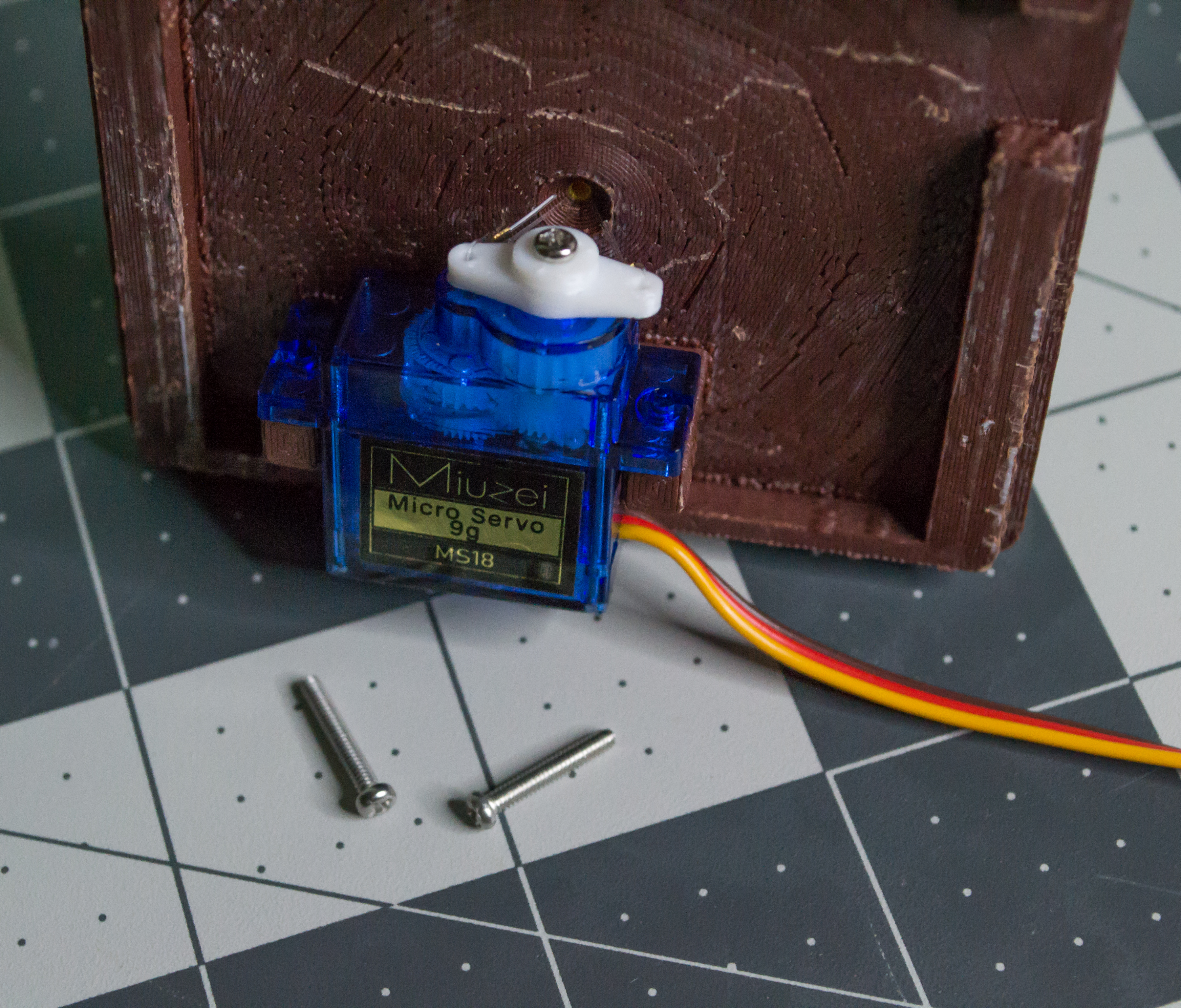
Place the servo into place so that the label (if you used Miuzei MS18 9 g servo) is facing down. Make sure that the arm component and motor output shaft are aligned with the center hole where the monofilament lines were pushed through. Next, use two M2, 12 mm machine screws to attach the servo to the legs and then use two M2 hex nuts to secure it in place.
 ➜
➜
 ➜
➜
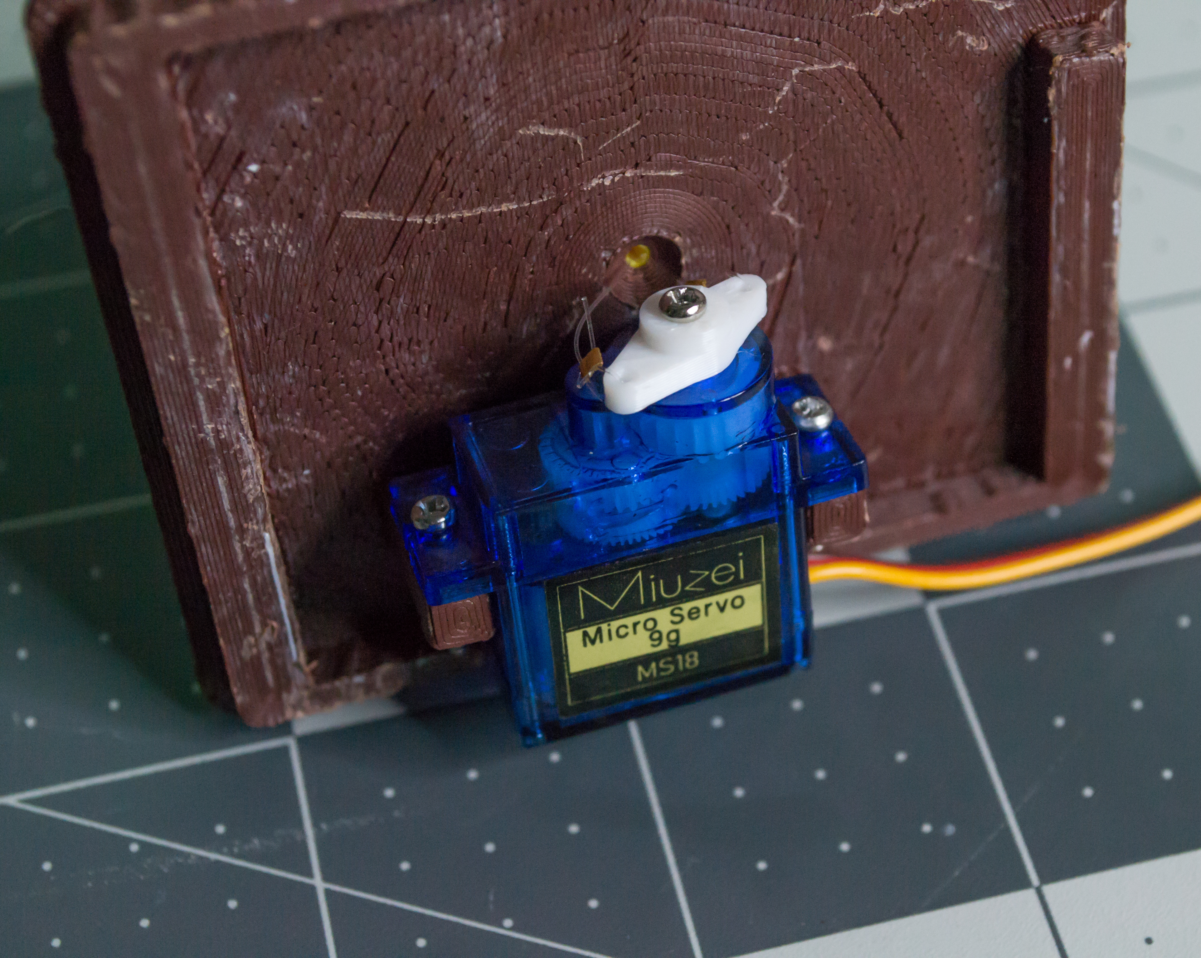
Check: The printed Arm should be centered on the servo shaft, secured with the servo horn screw, and both clear monofilament lines should exit cleanly from the top of the mast.
Lever and Motion Setup
Using the two monofilament lines coming from the top of the mast, insert one line into each hole on the bottom of the Lever. These holes pass through the Lever so the lines can exit on the other side and be secured later. Do not fully install the Lever yet; it will be pushed through the fulcrum in the next step.
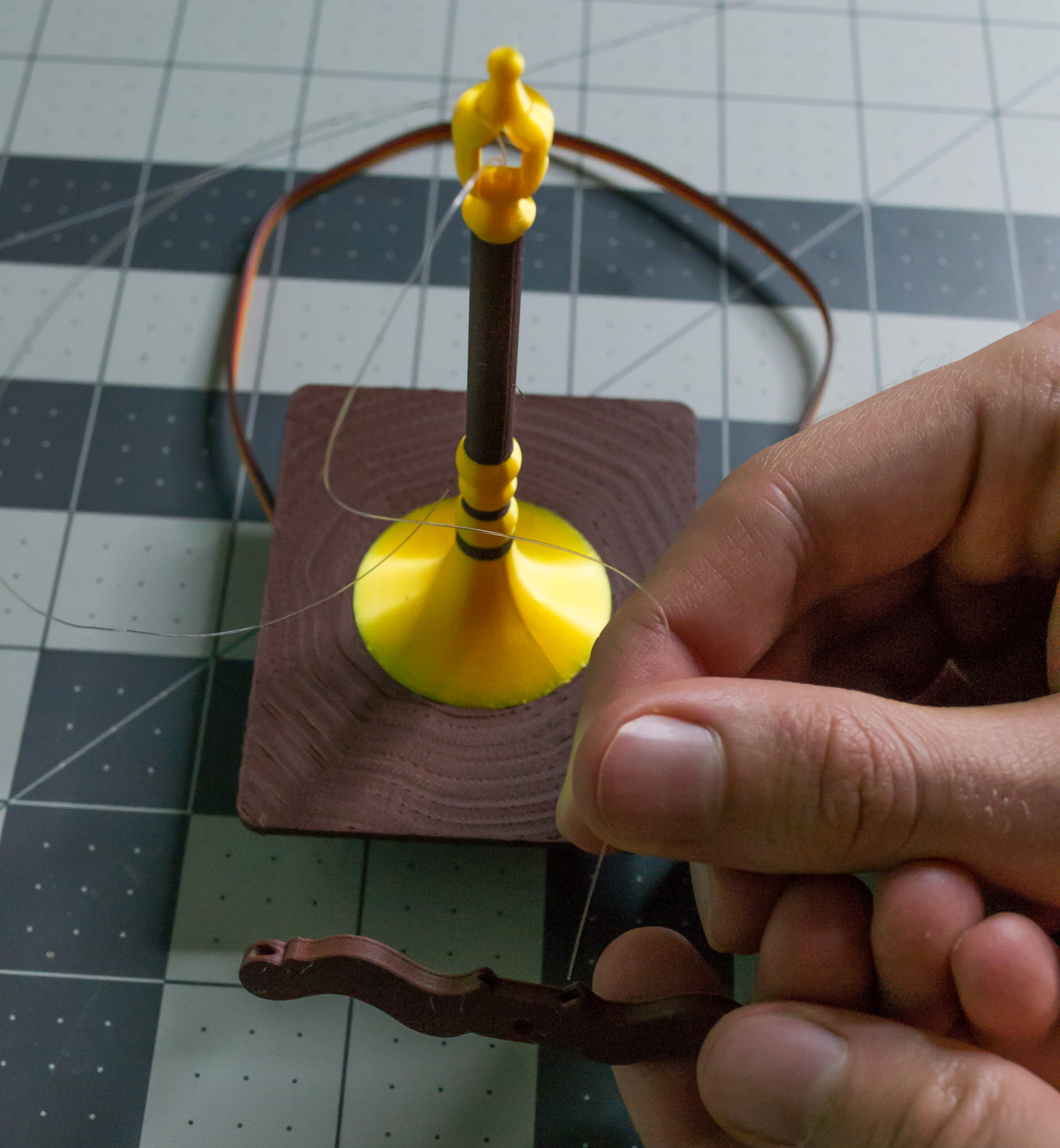 ➜
➜
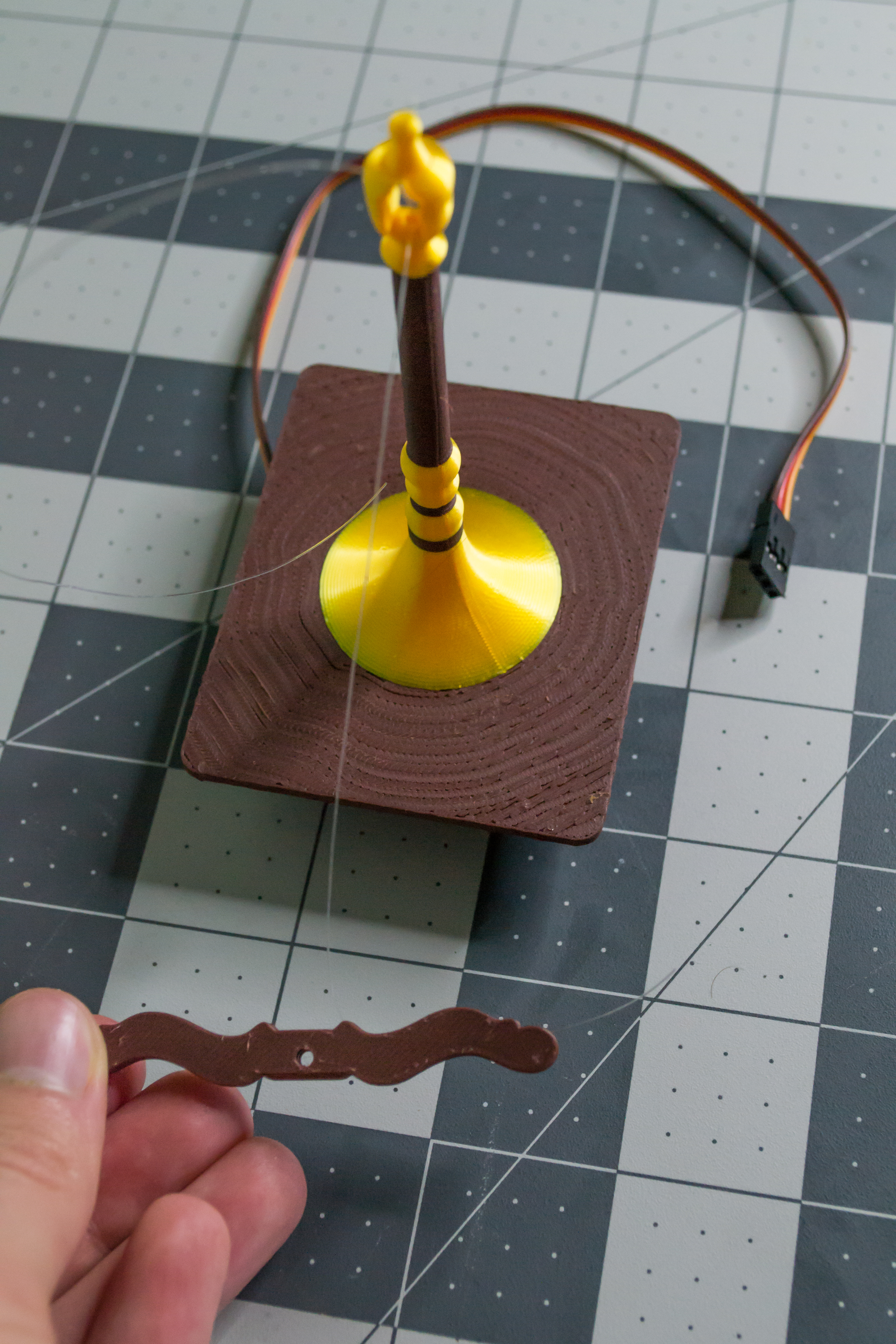 ➜
➜
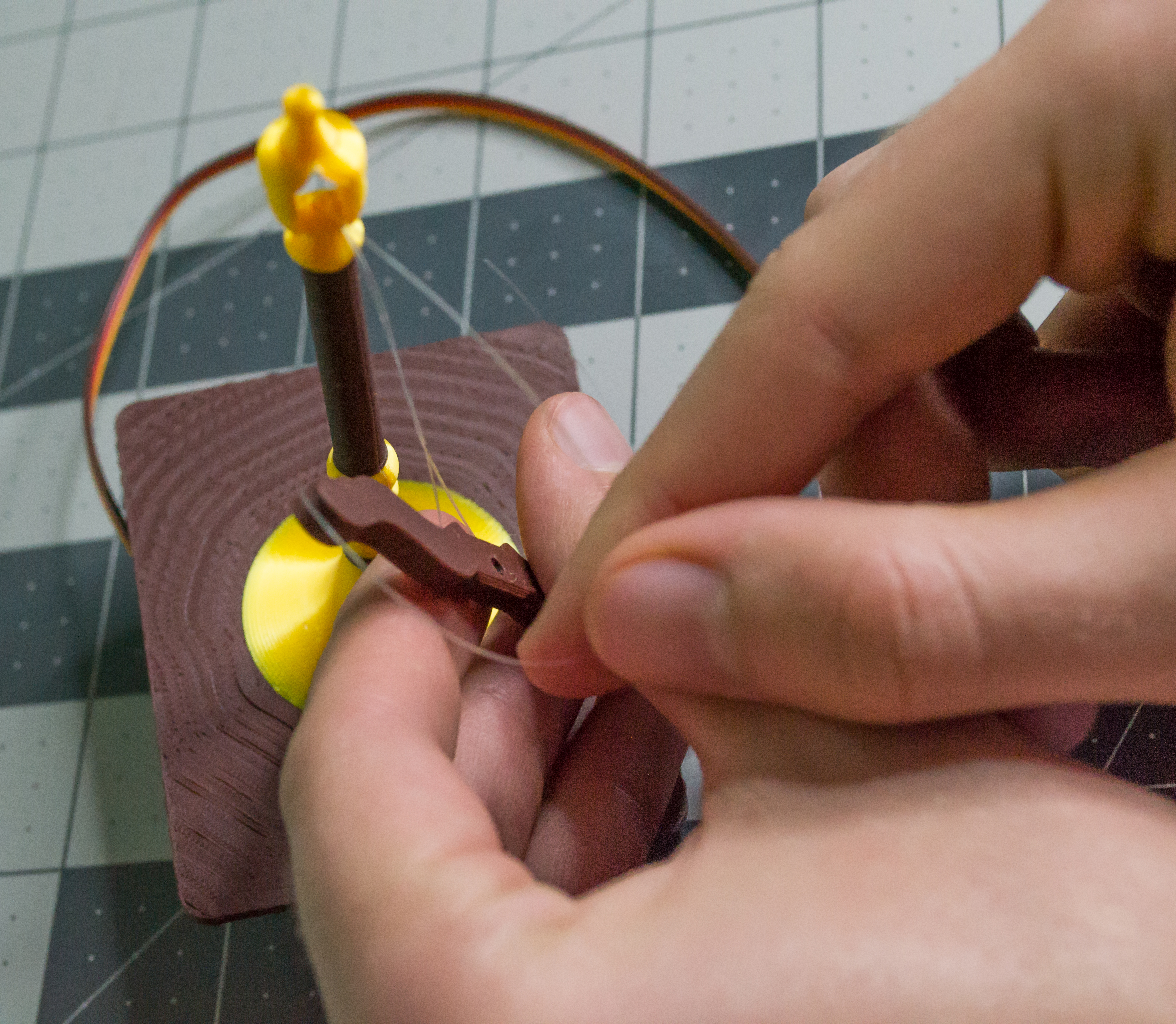
Now take one monofilament line, guide it through the fulcrum opening, and push the Lever through so it sits on the fulcrum.
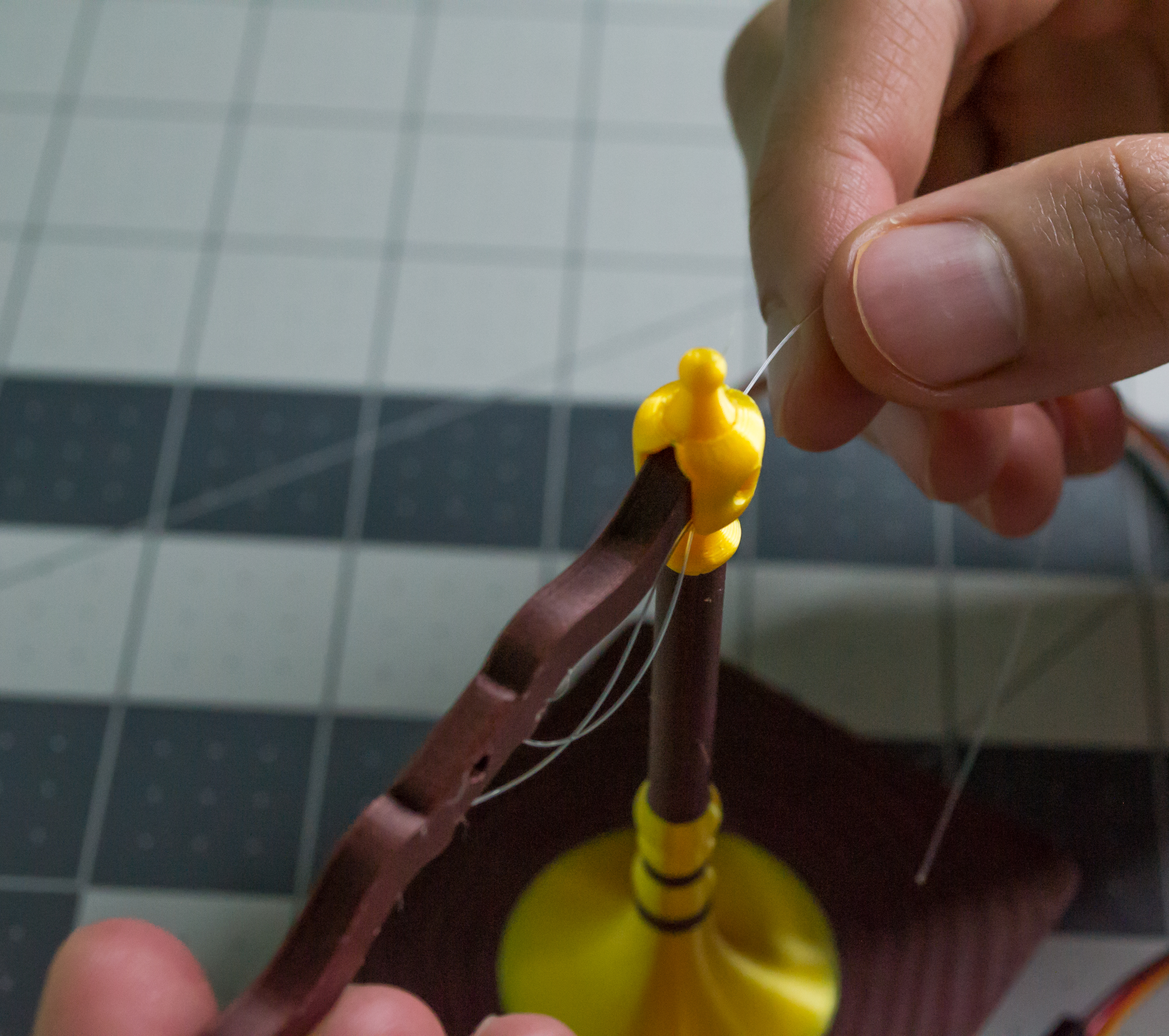 ➜
➜
Insert one M2, 16 mm machine screw through the fulcrum point, making sure the screw head/cross slot is on the front side where the back of the servo faces. Use two M2 hex nuts to secure it. Do not clamp the Lever too tightly. Instead, let the two M2 hex nuts lock against each other so the Lever can move freely without the screw coming loose.
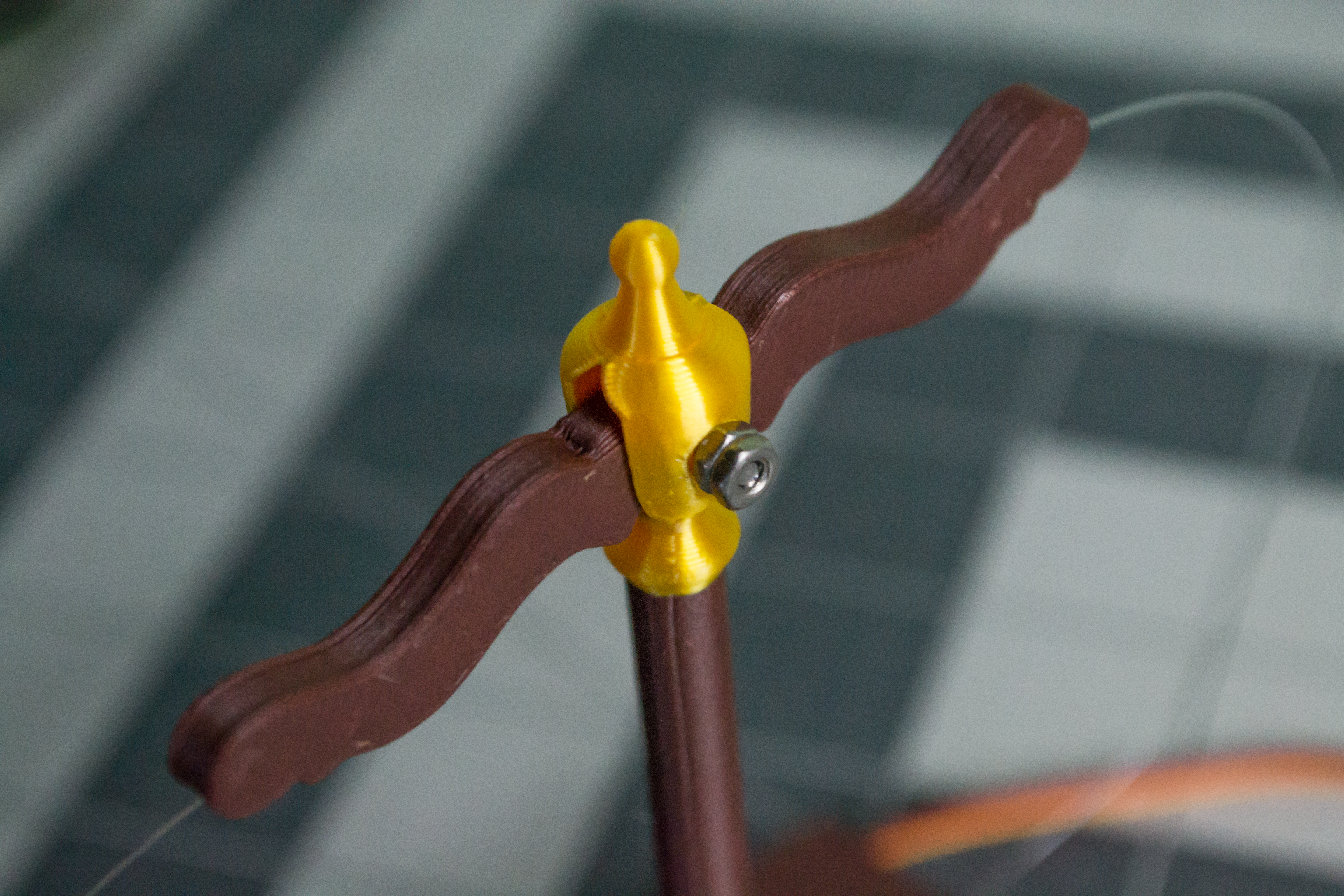
Check: The Lever should pivot freely on the M2, 16 mm machine screw. The two M2 hex nuts should lock against each other, not clamp the Lever tightly.
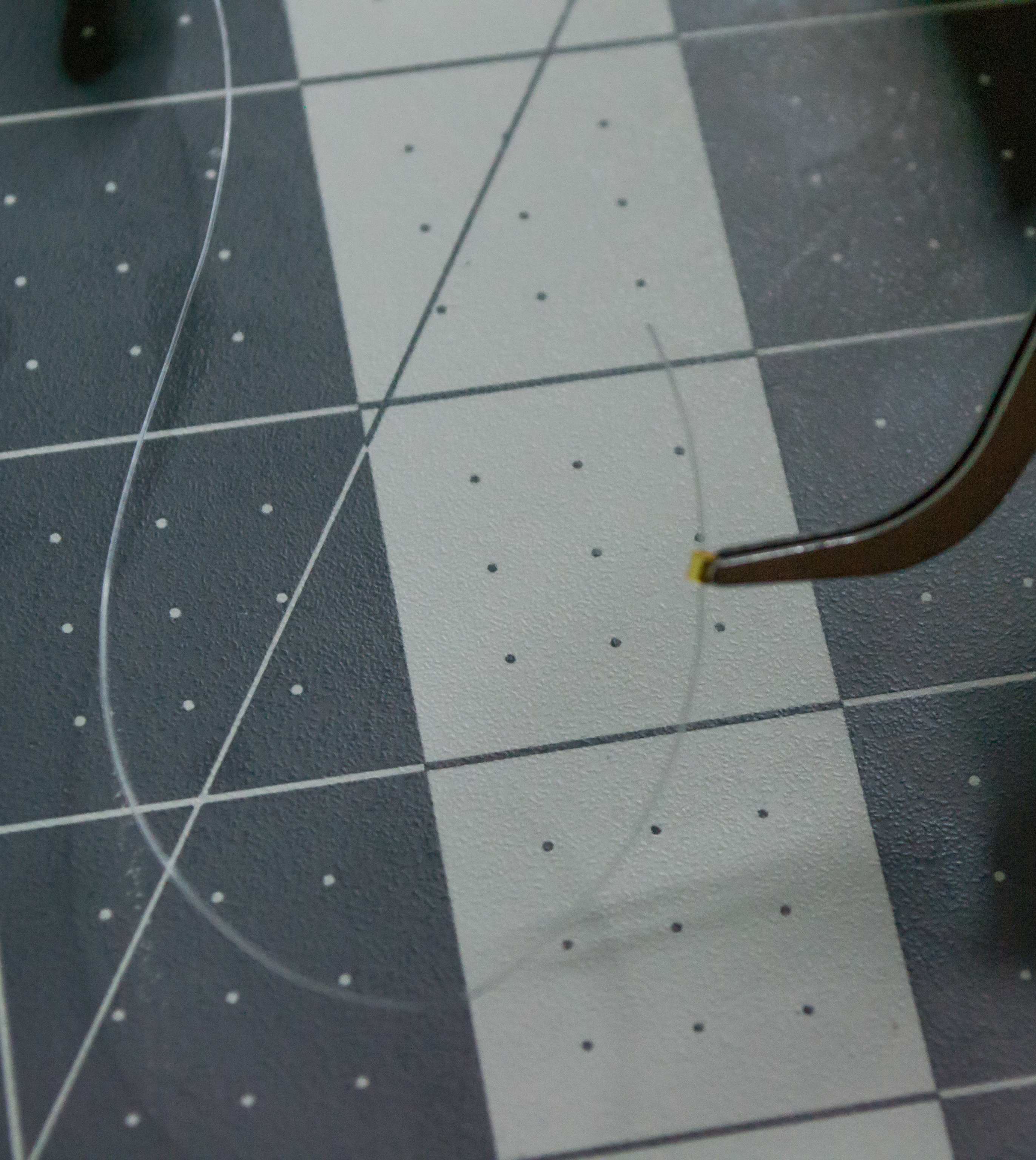
Take the Top/Scale assembly with the Lever and monofilament, then choose one side to start with. Add one small gold crimp bead to the line, create a loop, and move the bead as close to the Lever as possible.
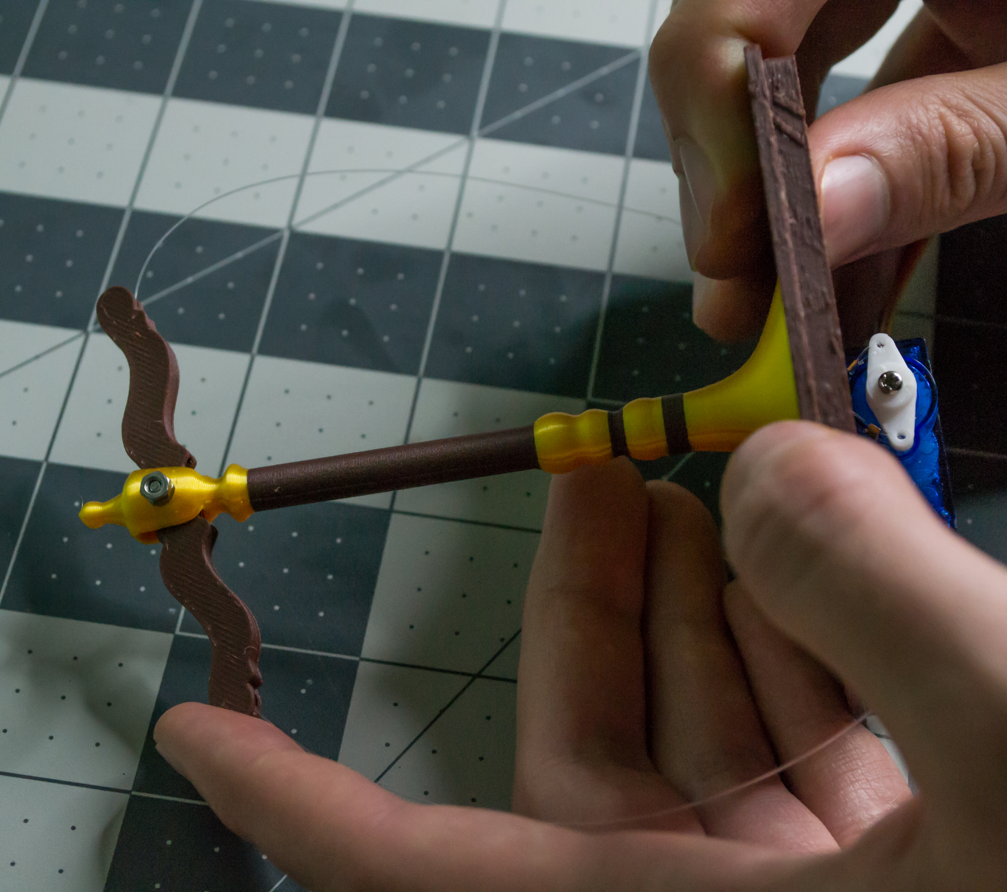 ➜
➜
 ➜
➜
 ➜
➜
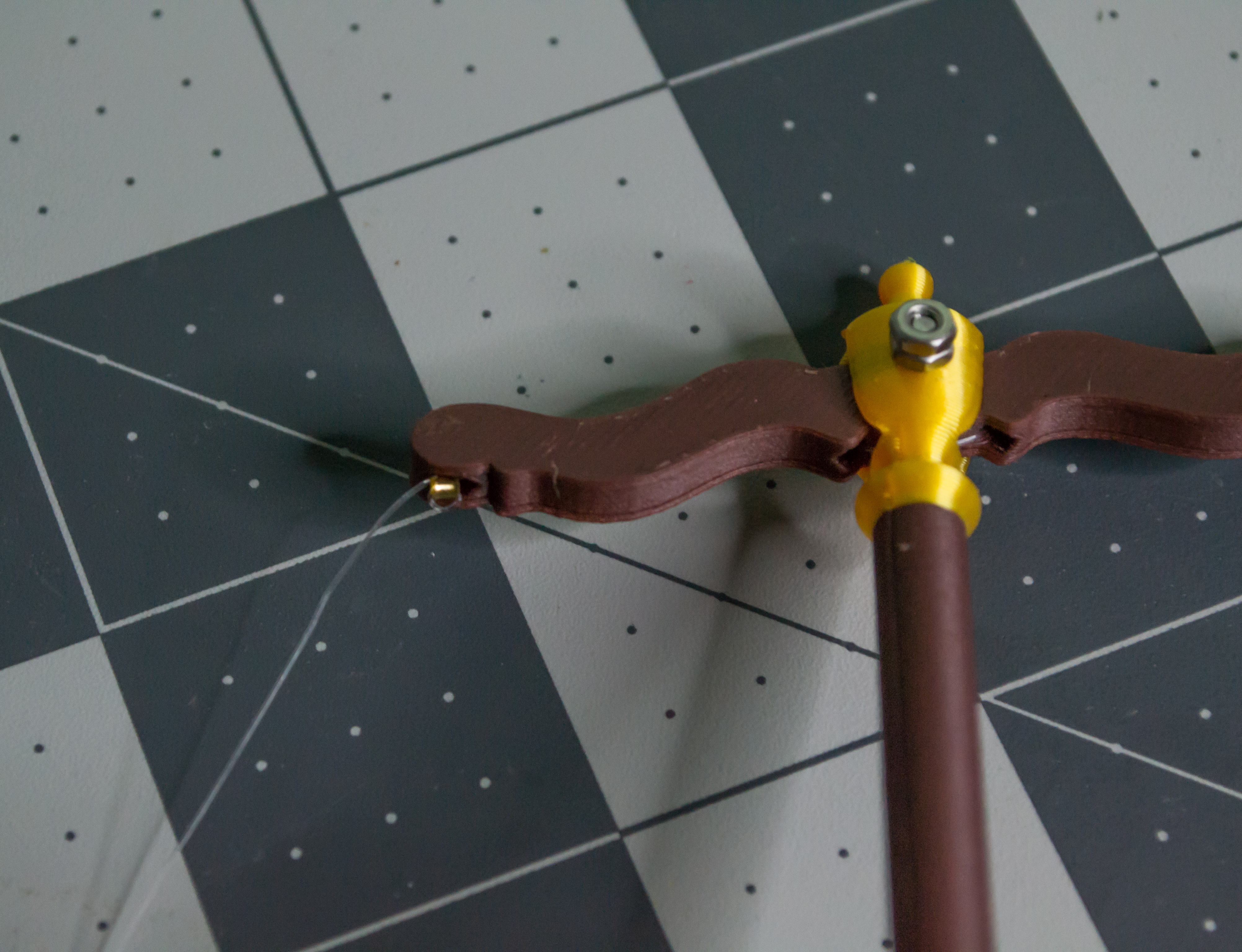
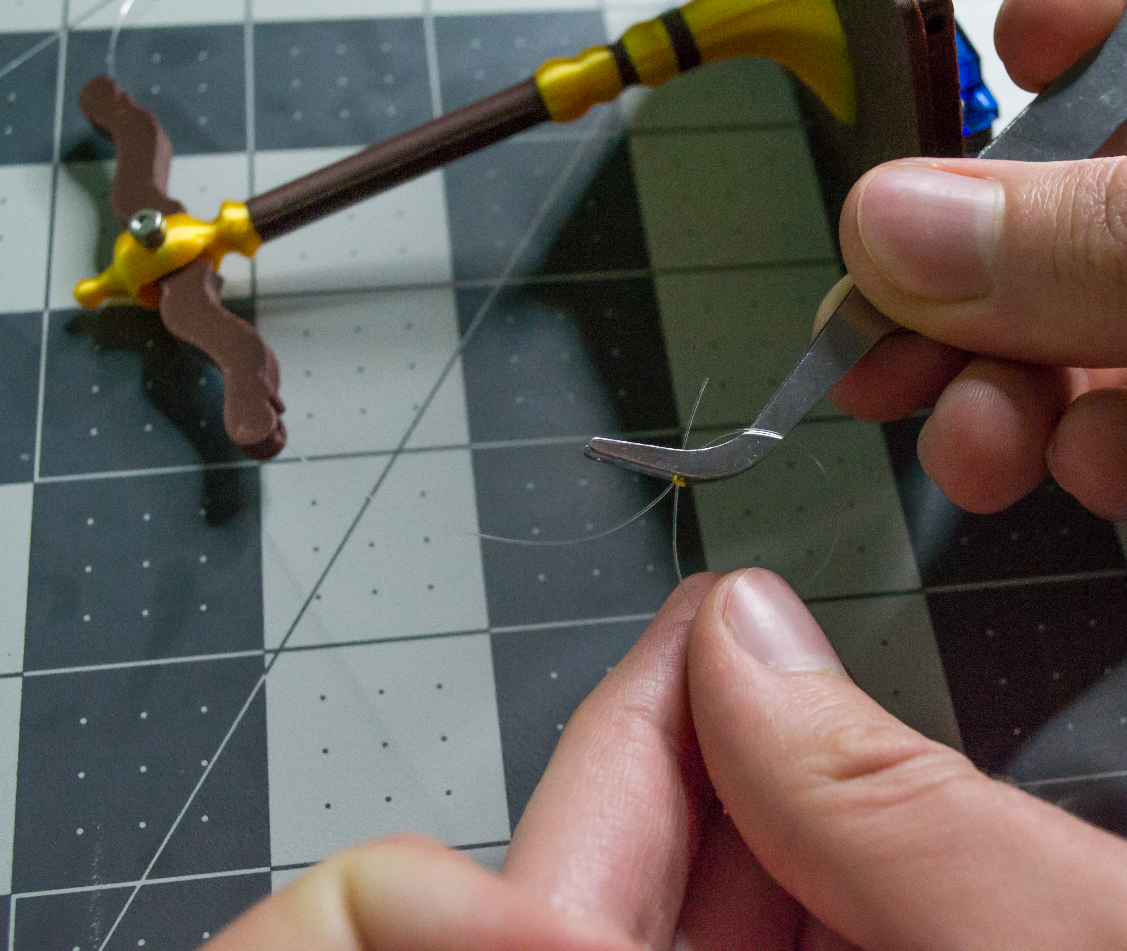
It may help to slightly reposition the servo Arm and Lever so they are as close to each other as possible. This helps set the tension. The bead should sit slightly inside the Lever, which hides it and reduces the tension a little. A small tool placed in the extra loop around the bead can help push the bead down without closing the loop too early; then remove the tool and pull the line tight.
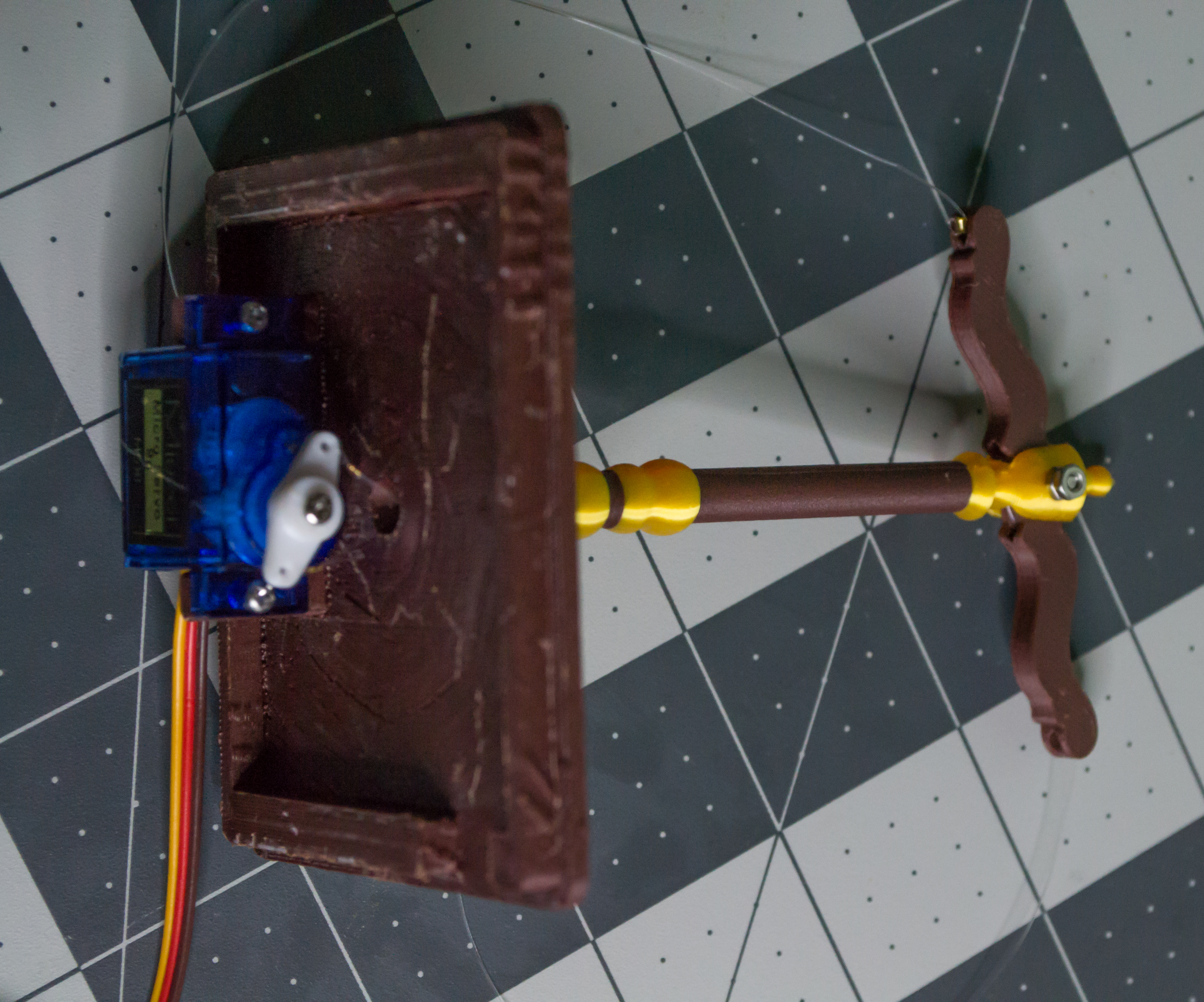
Crimp the bead, then push it into the Lever. Repeat this on the other side. You should now have a movable lever assembly.
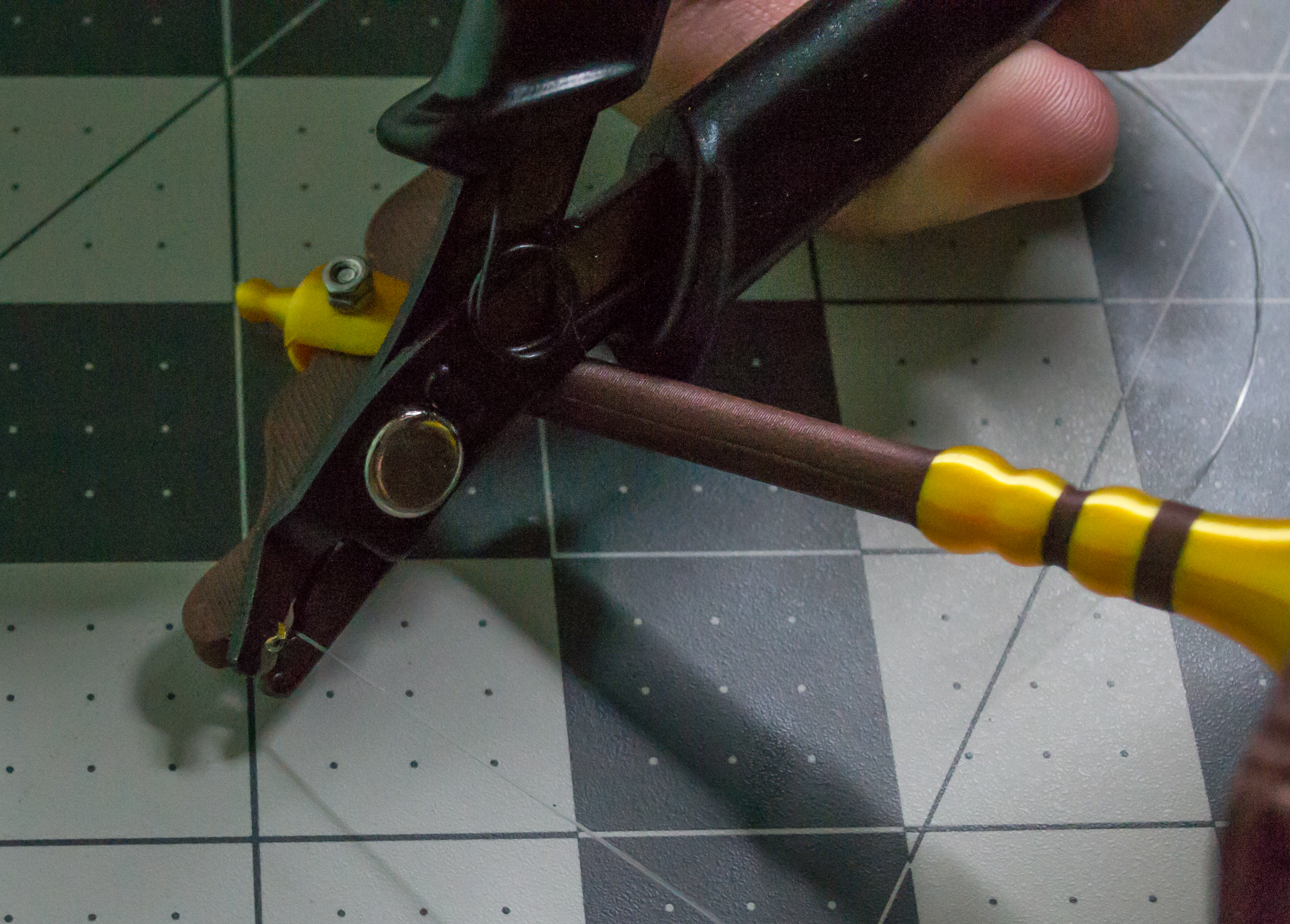 ➜
➜
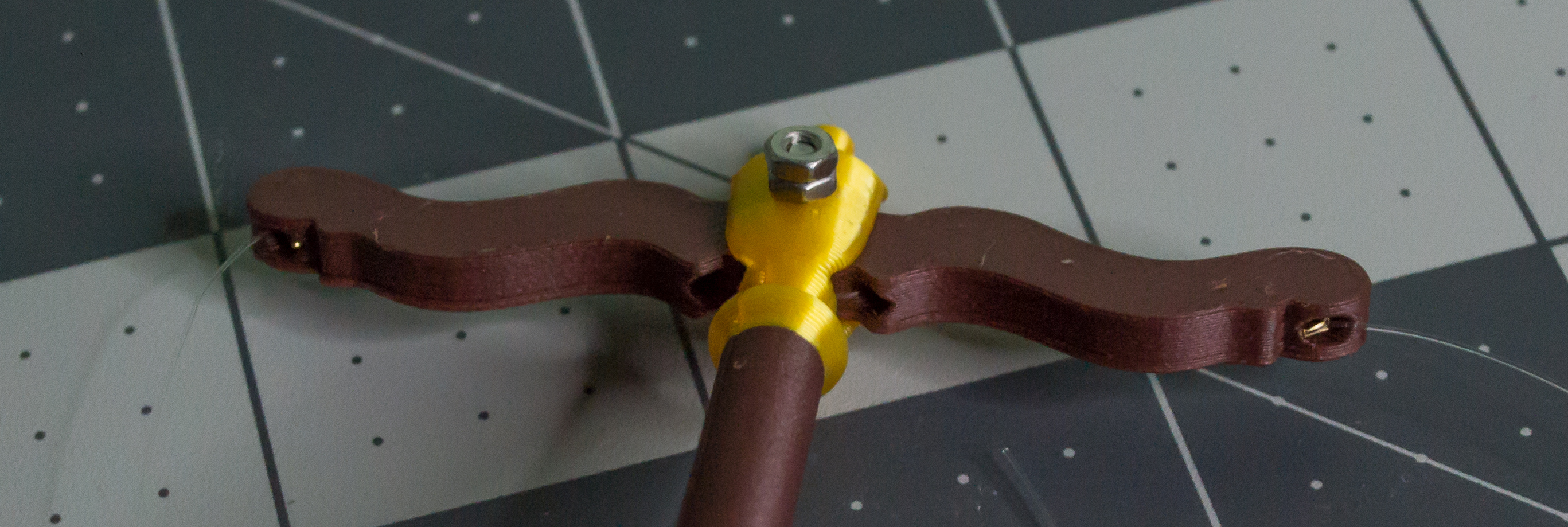
Before continuing, test the motion. Power the board from USB Mini-B or insert three 1.2 V AAA rechargeable batteries. Adjust the servo range if needed before anything binds or breaks.
Check: Before moving on, power the board briefly and make sure the servo can move the Lever without binding, slipping, or pulling the clear monofilament line too tightly.
Next, put one gold clamshell bead tip onto one line coming from the Lever. Then add one small gold crimp bead after it and create a loop around the crimp bead.
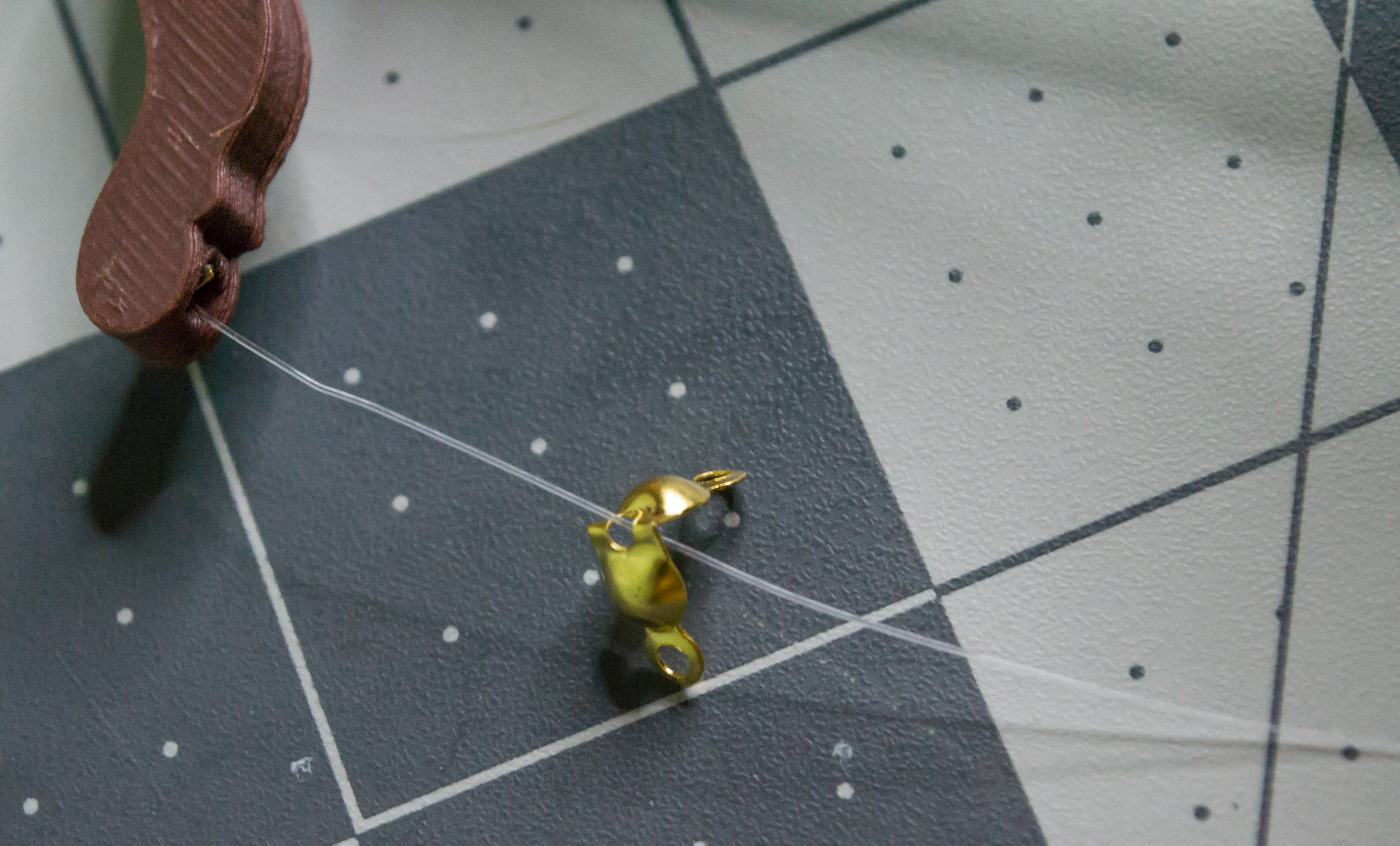 ➜
➜
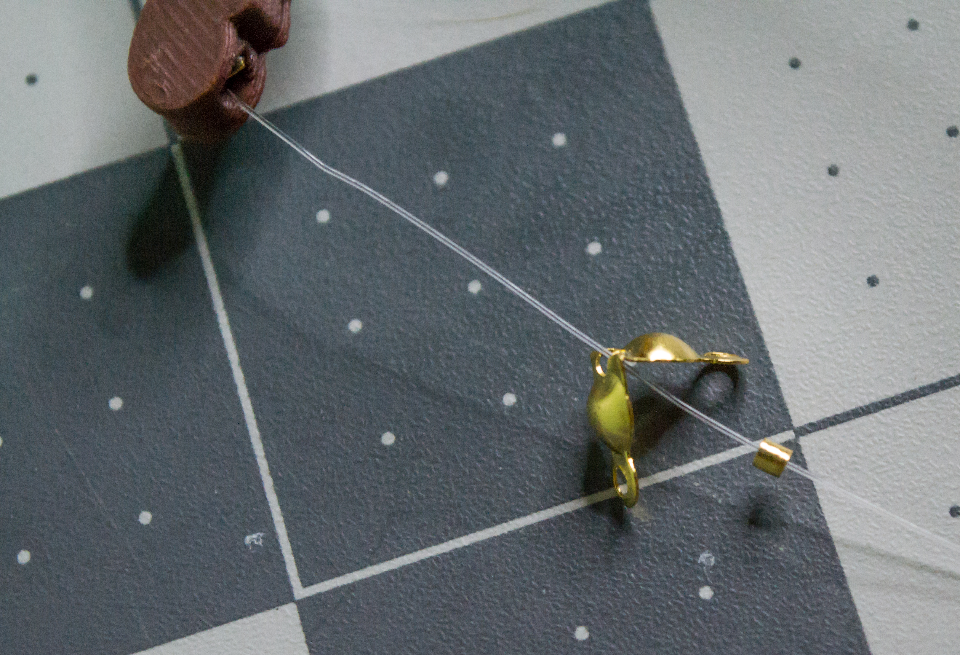 ➜
➜
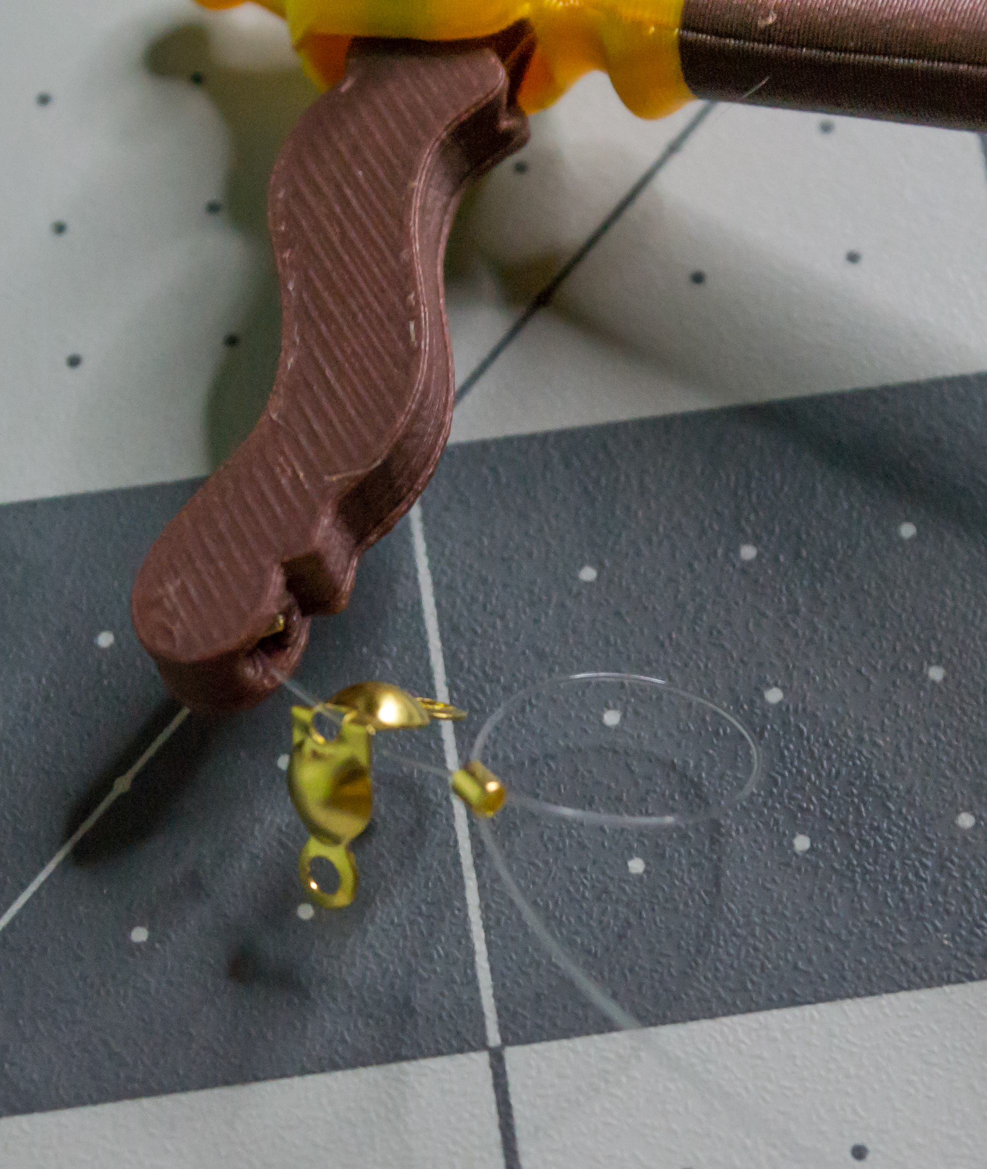
Then do the same on the other side.
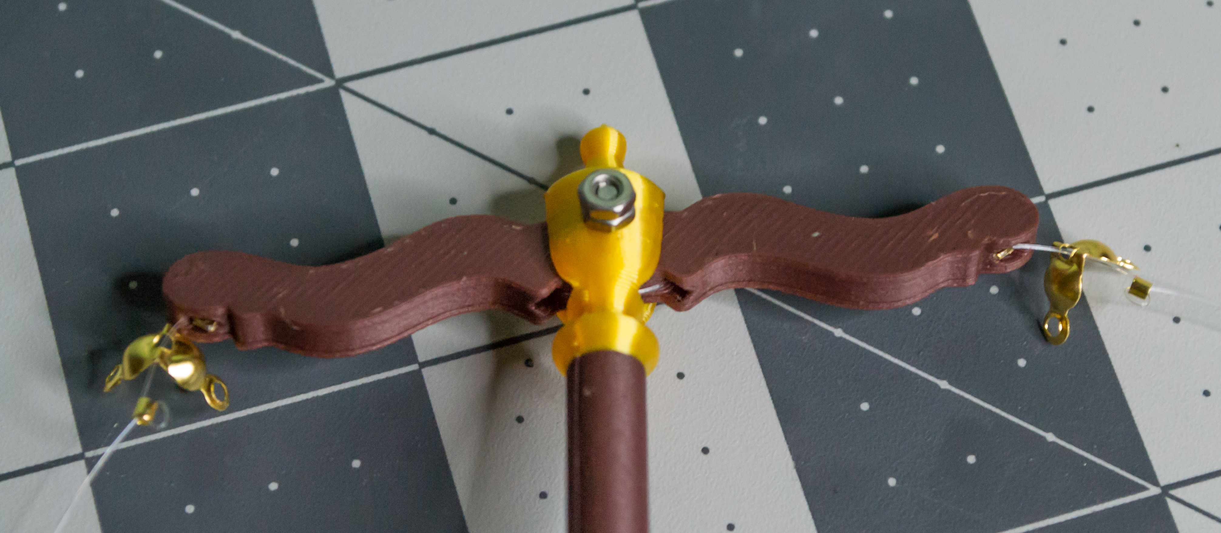 ➜
➜
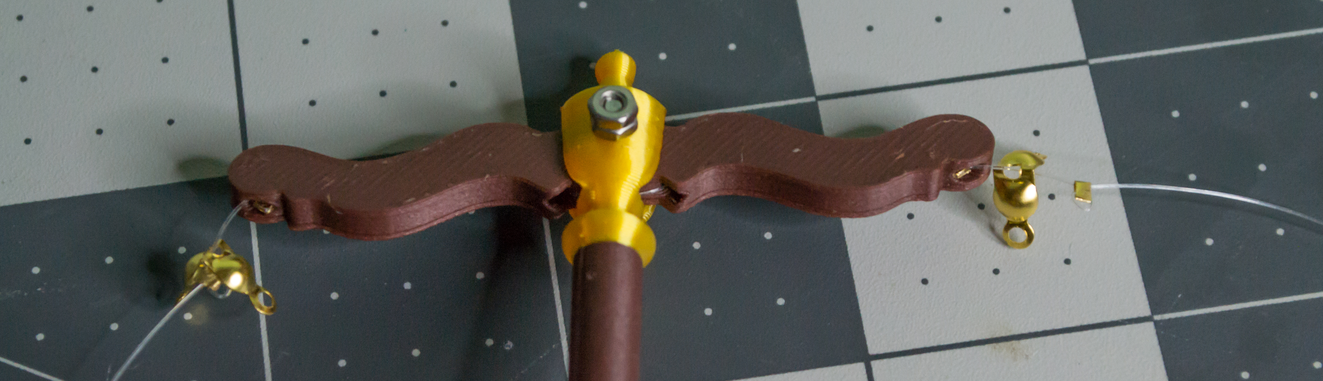
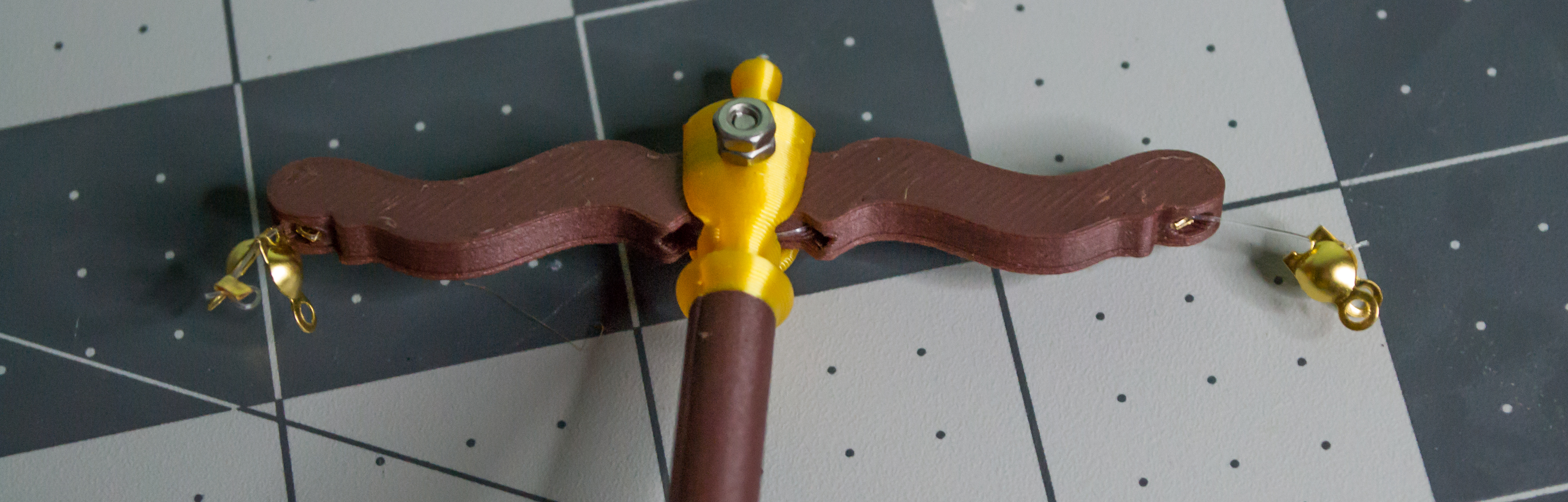
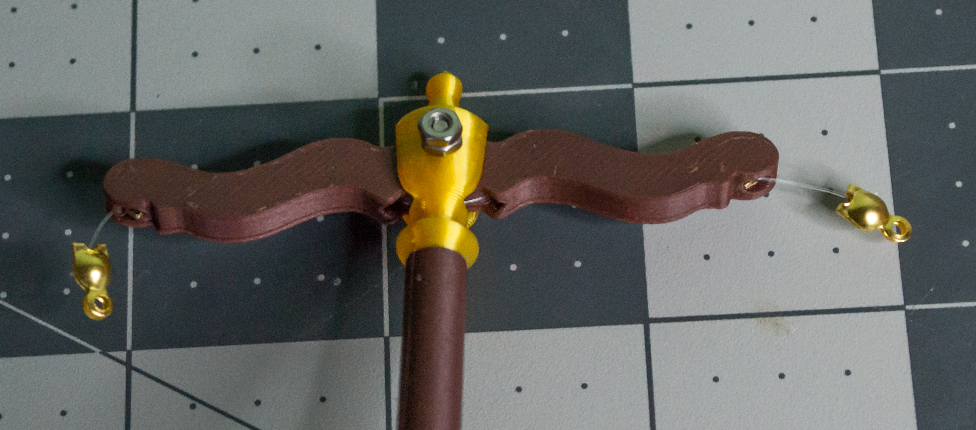
Adjust both small gold crimp beads so they are at the same height, then crimp them in place. Cut off the excess monofilament and close the clamshell bead tips by hand.
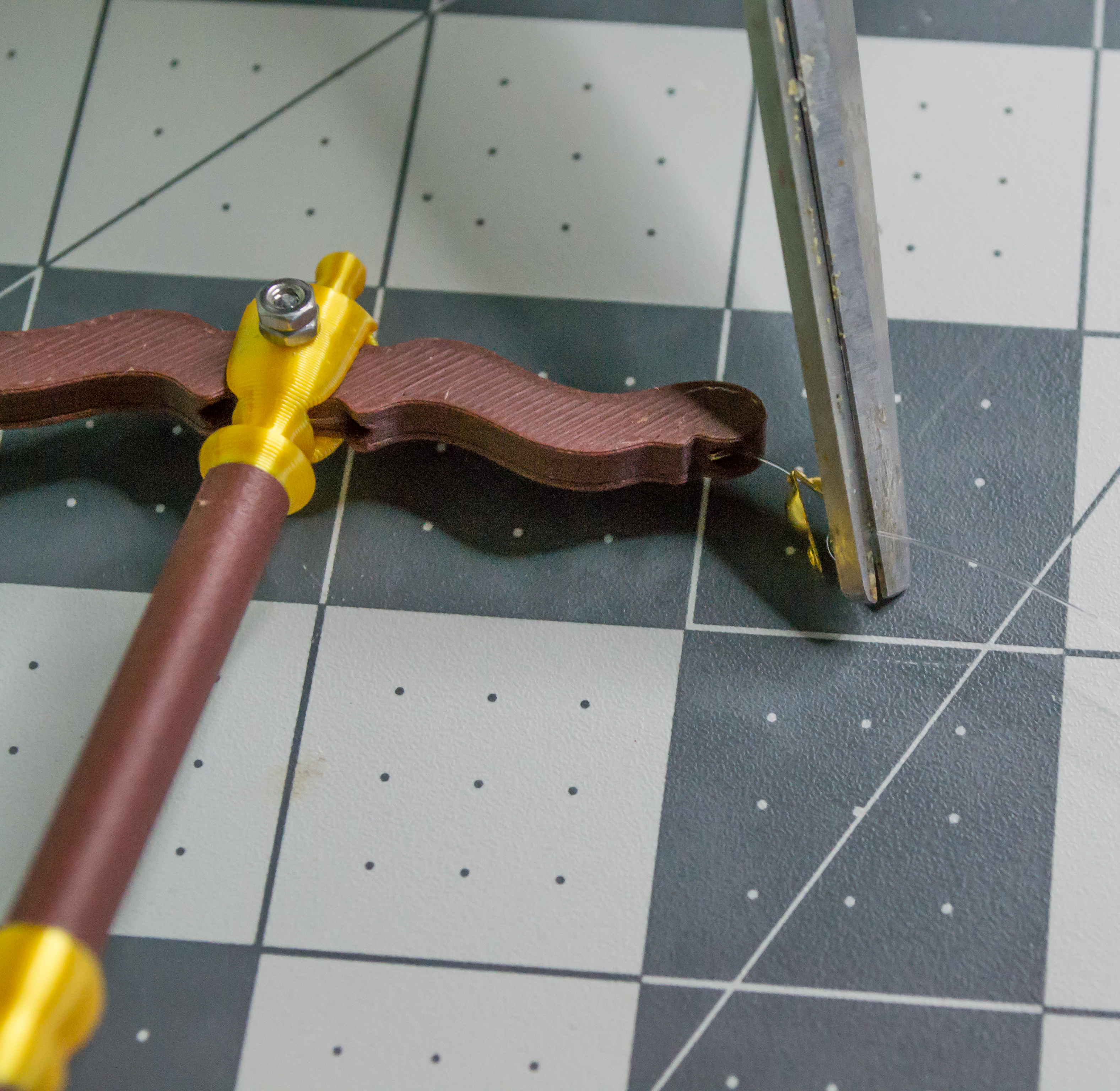 ➜
➜
 ➜
➜
Top Assembly and Wiring
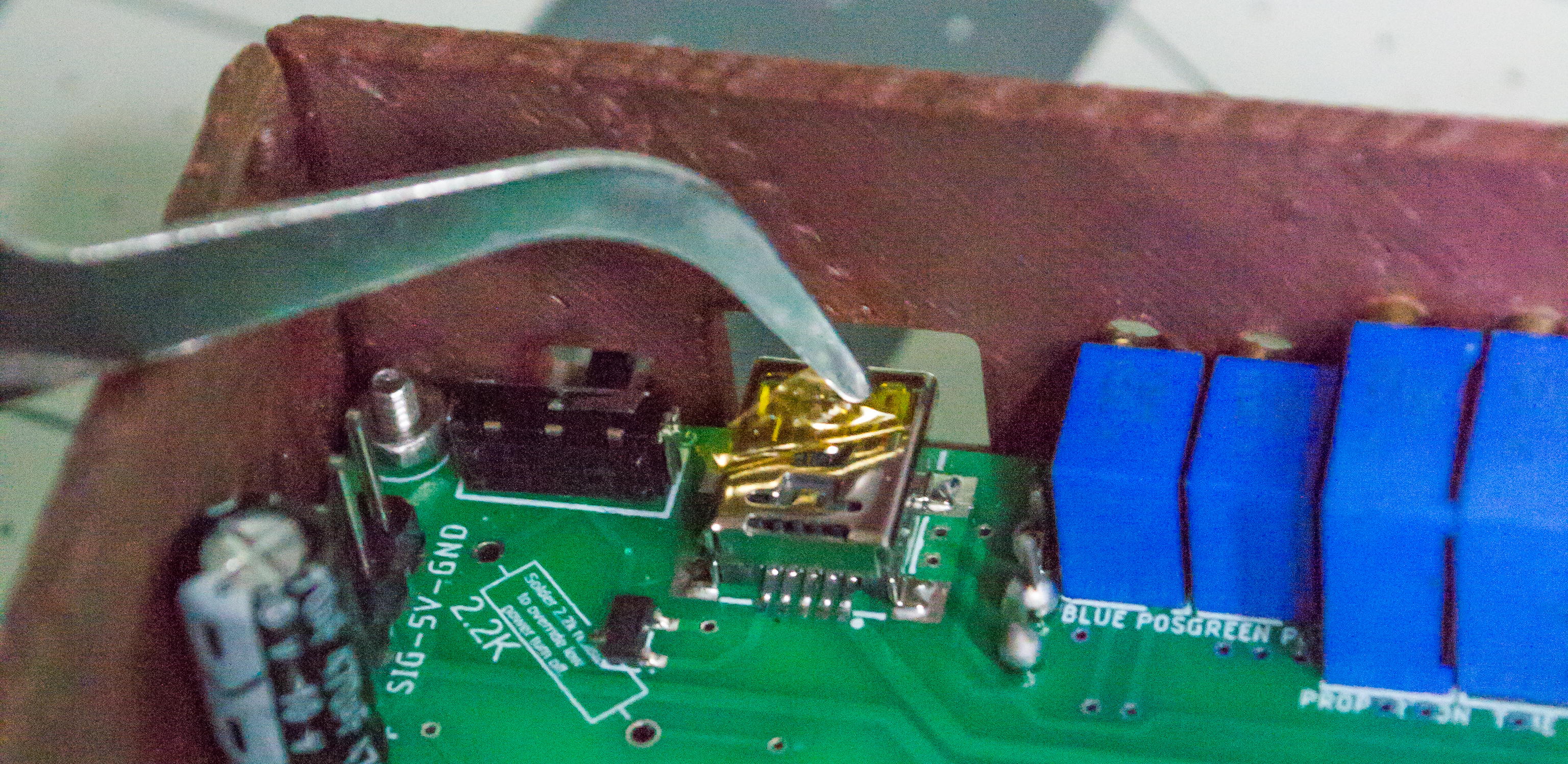
Before attaching the Top/Scale component to the Body, do a few checks. First, remove the yellow film from the USB Mini-B connector. Then connect the servo to the 3-pin header. The controller board labels the pins as Signal, 5 V, and GND, and it also includes the common servo wire colors. For the Miuzei servo, connect yellow to signal, red to 5 V, and brown to GND.
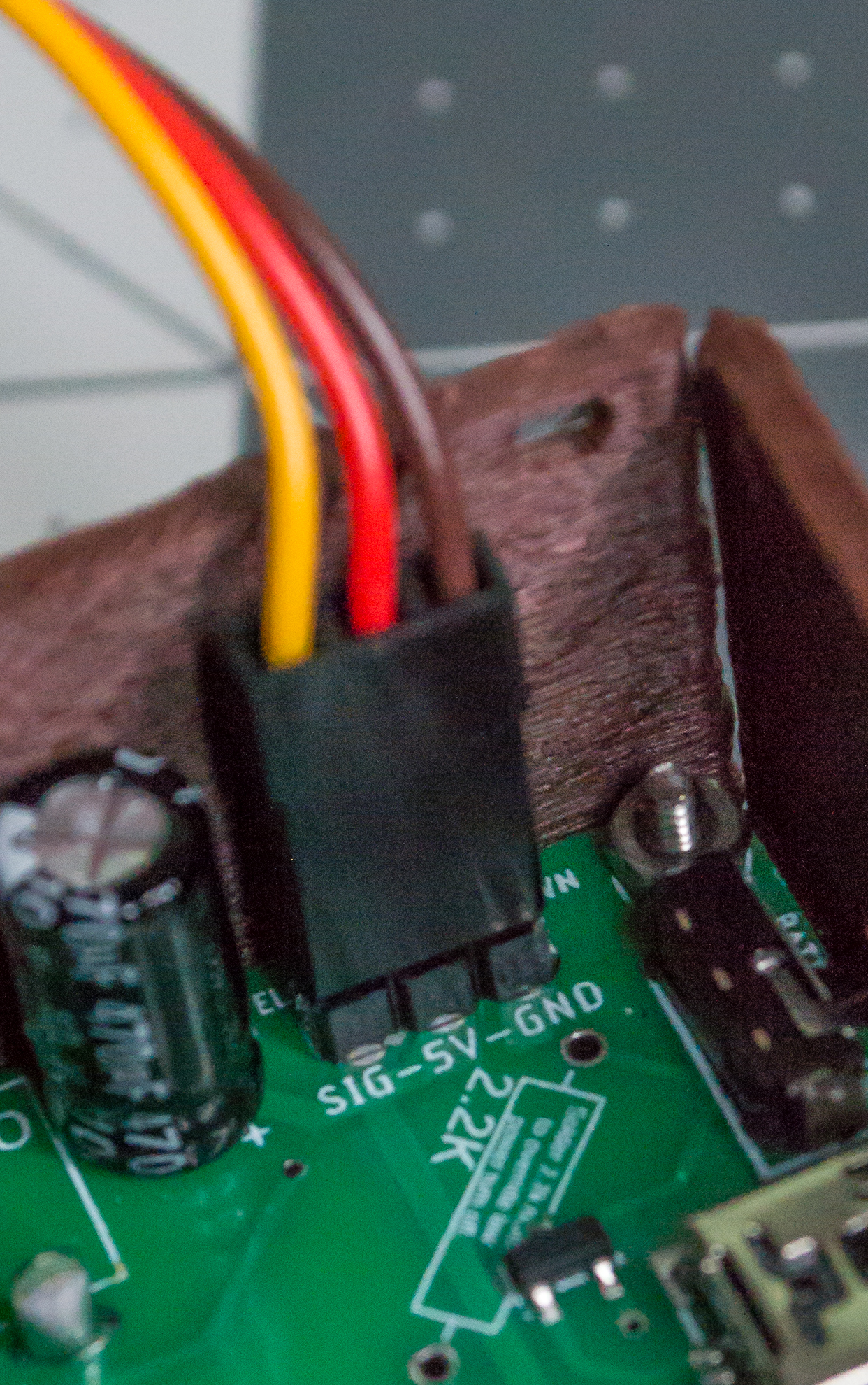
Check: The servo connector should be wired yellow to
Signal, red to5 V, and brown toGND, and the servo lead should be tucked away from the moving Arm.
Carefully tuck the servo wire inside the Body so it does not interfere with the servo motion. Then place the Top/Scale component onto the Body and get four M2, 8 mm machine screws ready. Install two M2, 8 mm machine screws on the left side and two on the right side.
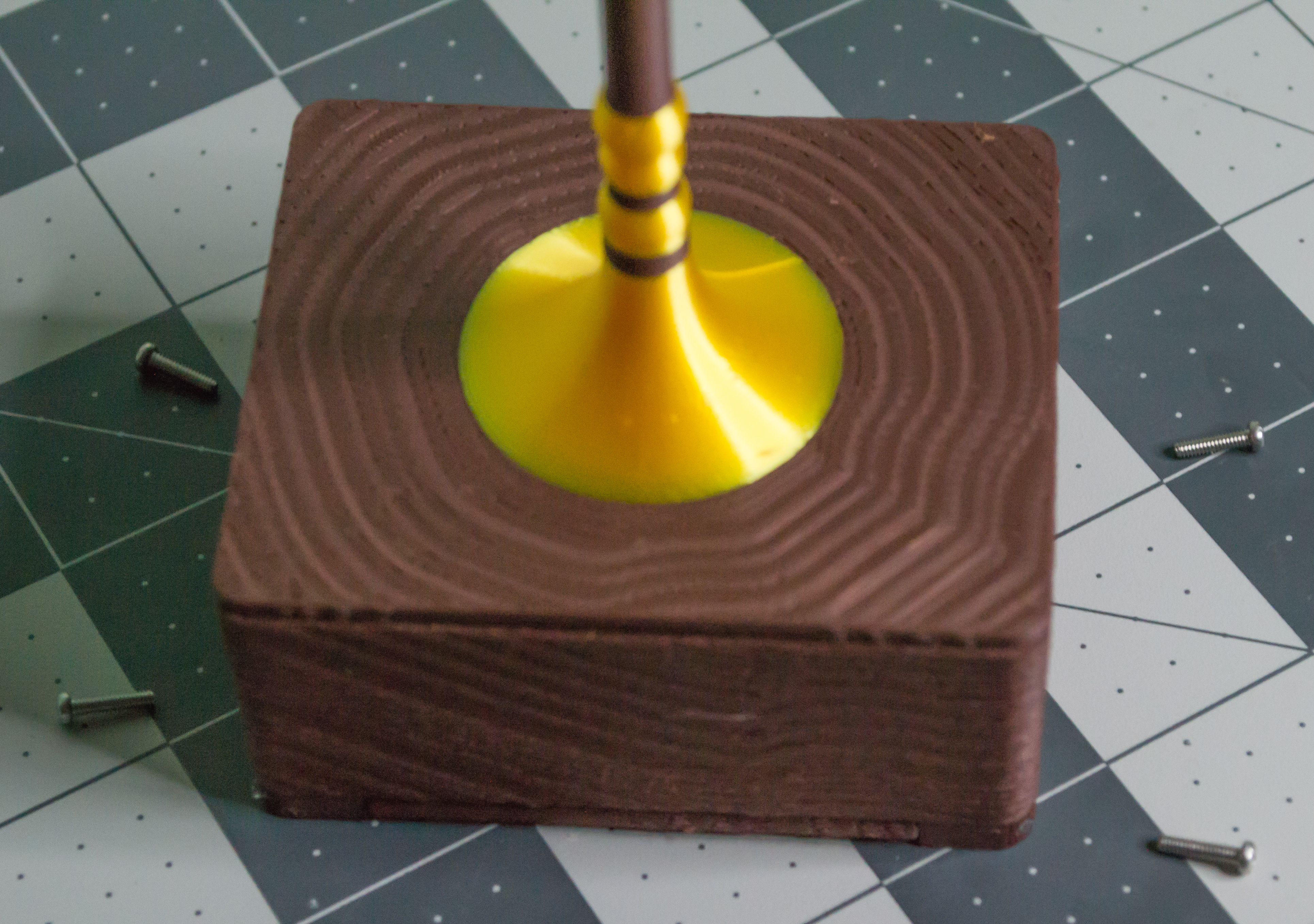 ➜
➜
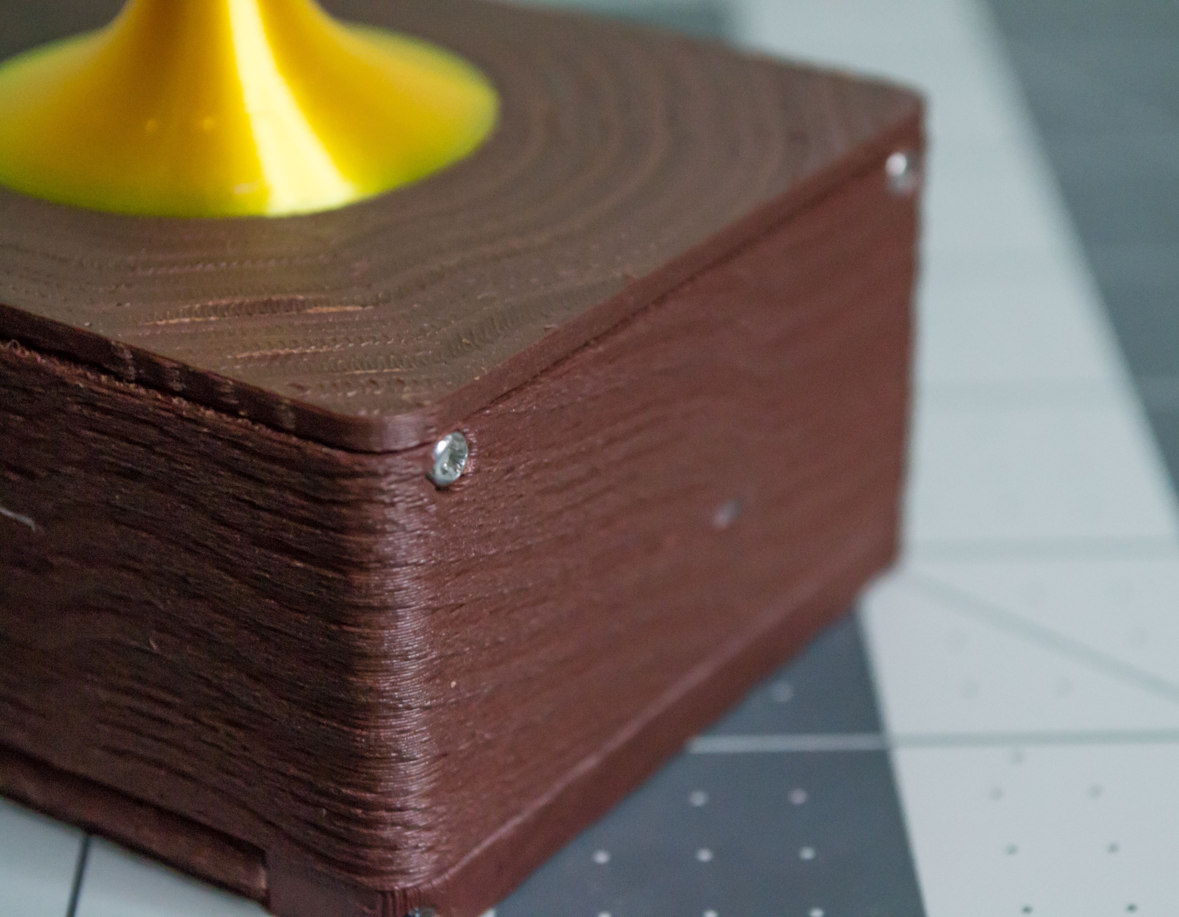
Check: The Top/Scale component should sit flush on the Body, and all four M2, 8 mm machine screws should be installed. Make sure the servo wire bends and has a safe spot to reside inside.
Hanging Plates and Final Closure
Next, attach the two gold plates to the Lever assembly. These plates hold the ideas, choices, or priorities you want to weigh.
Start with one printed Plate. Cut one monofilament line approximately 15 cm long and push it through one of the small holes. Add one small gold crimp bead and pass both ends of the line through it. Then take the short end and loop it through again so it will not slip. Tighten the loop and crimp the bead.
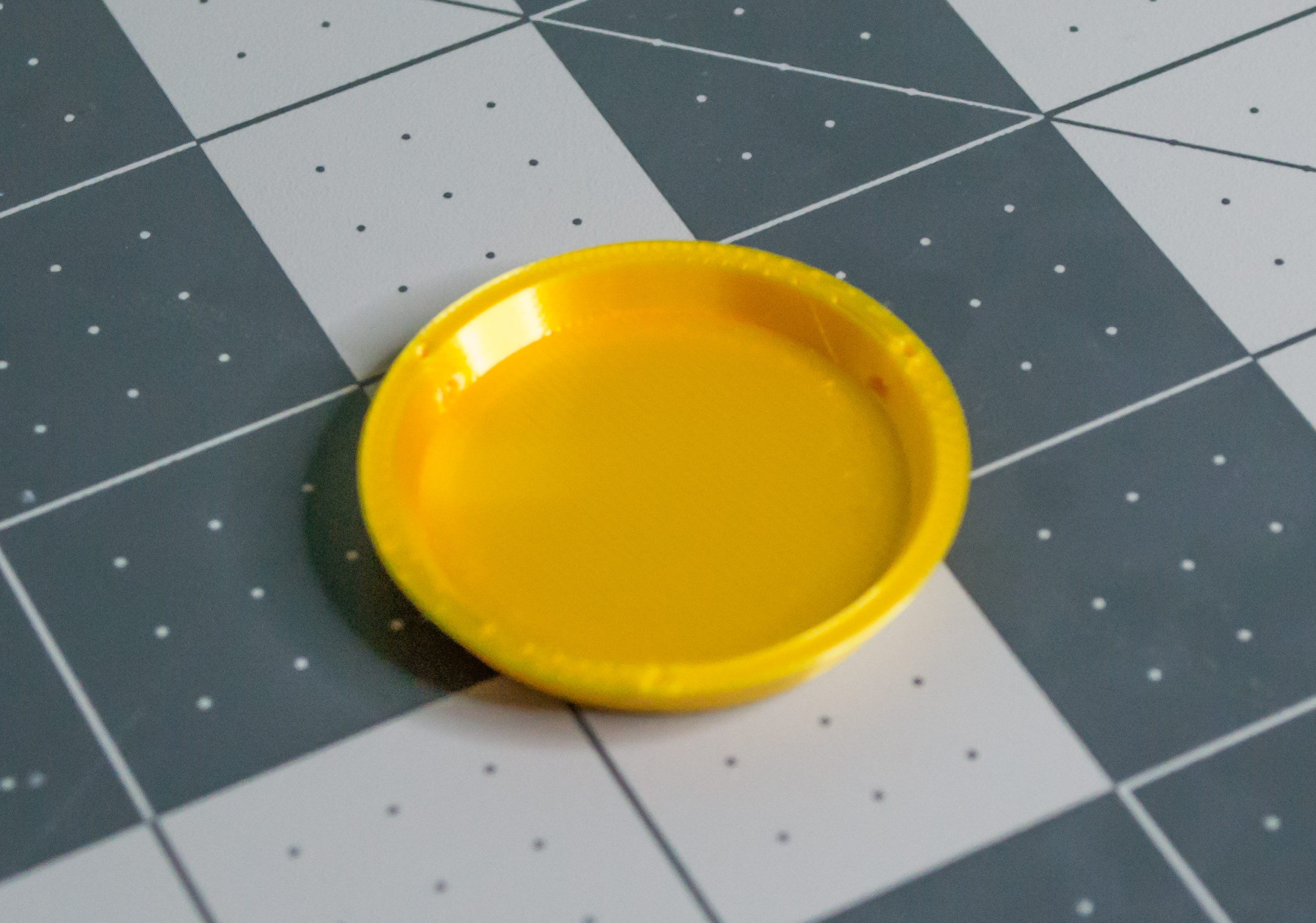 ➜
➜
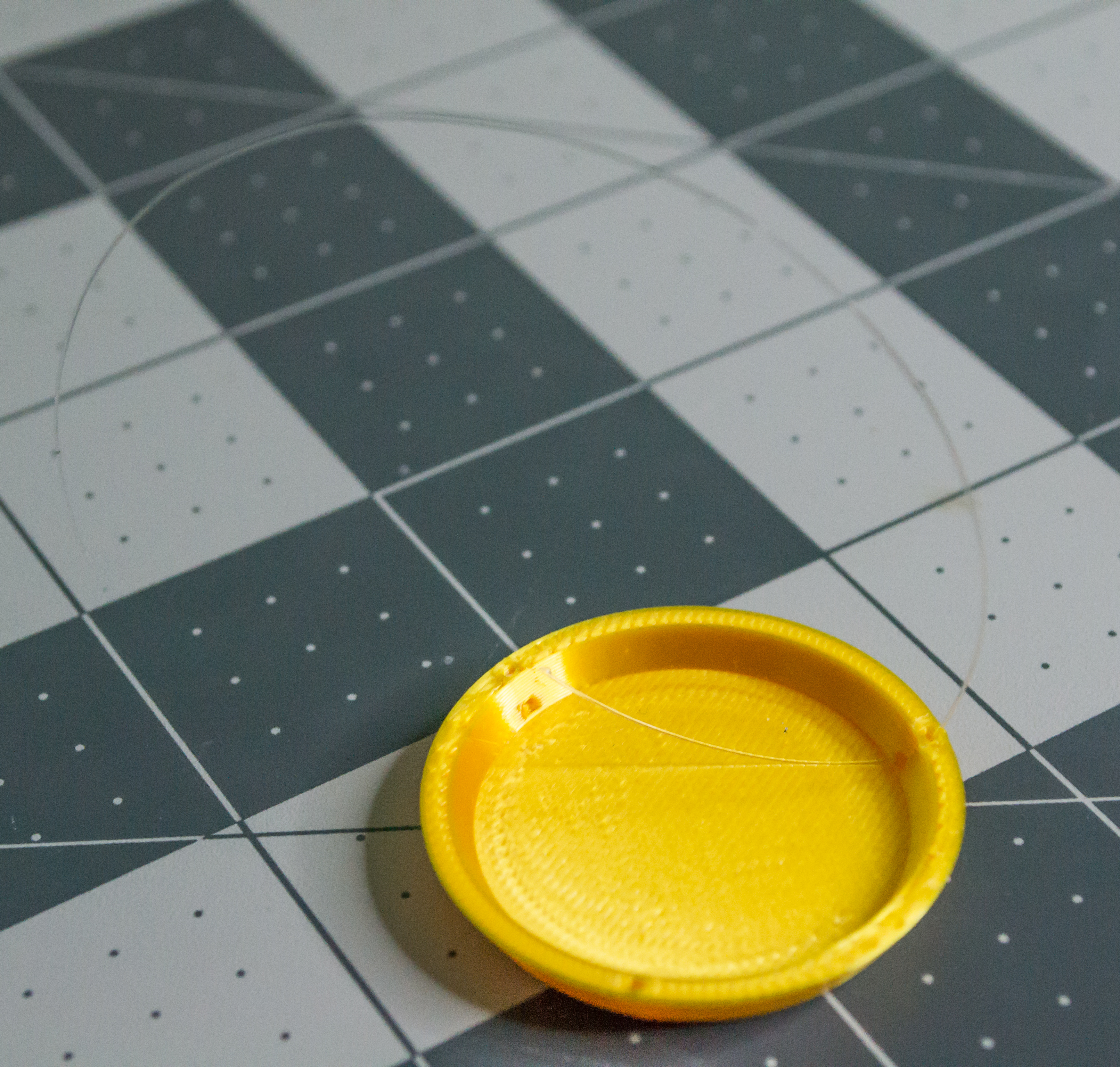 ➜
➜
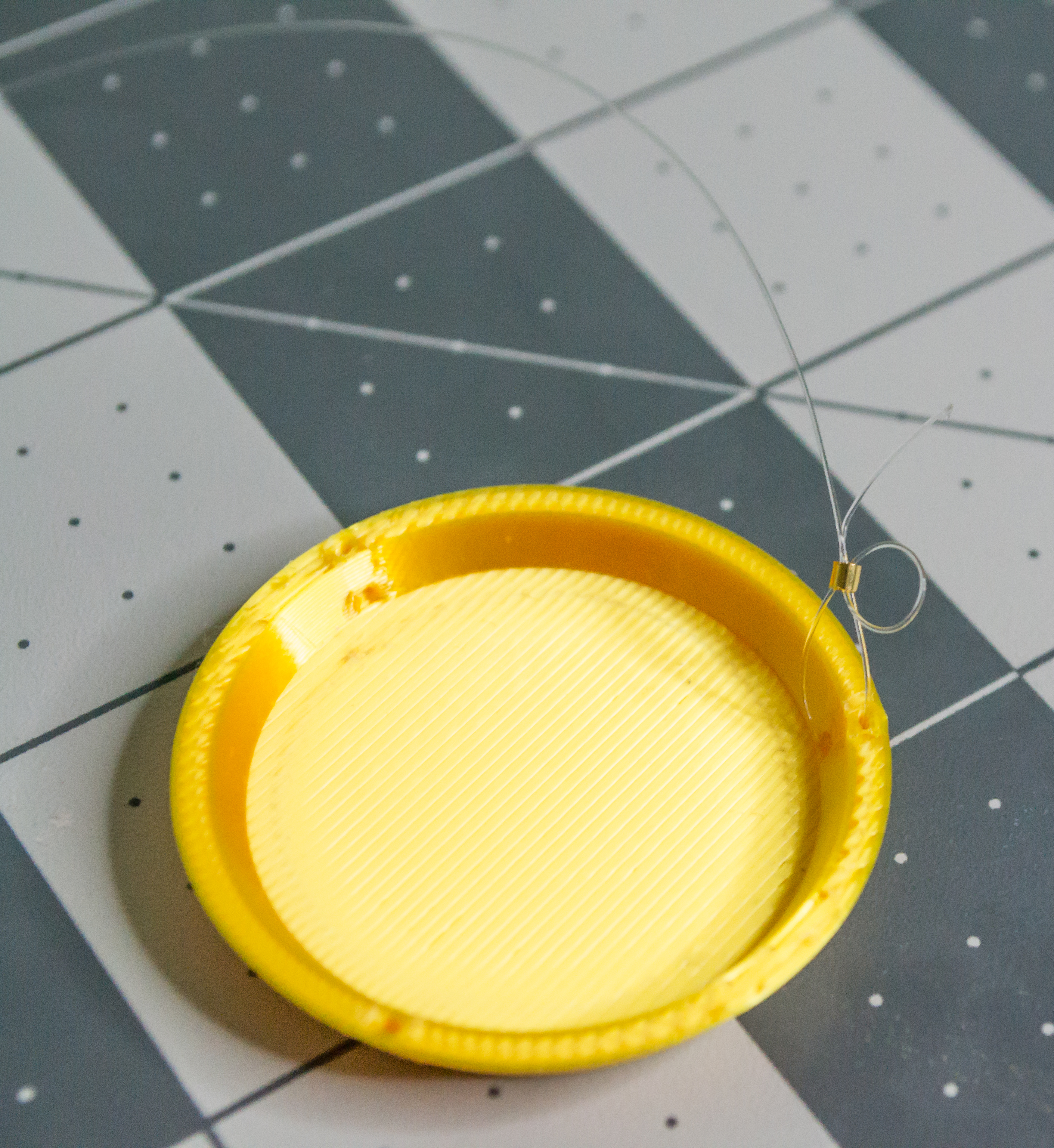 ➜
➜
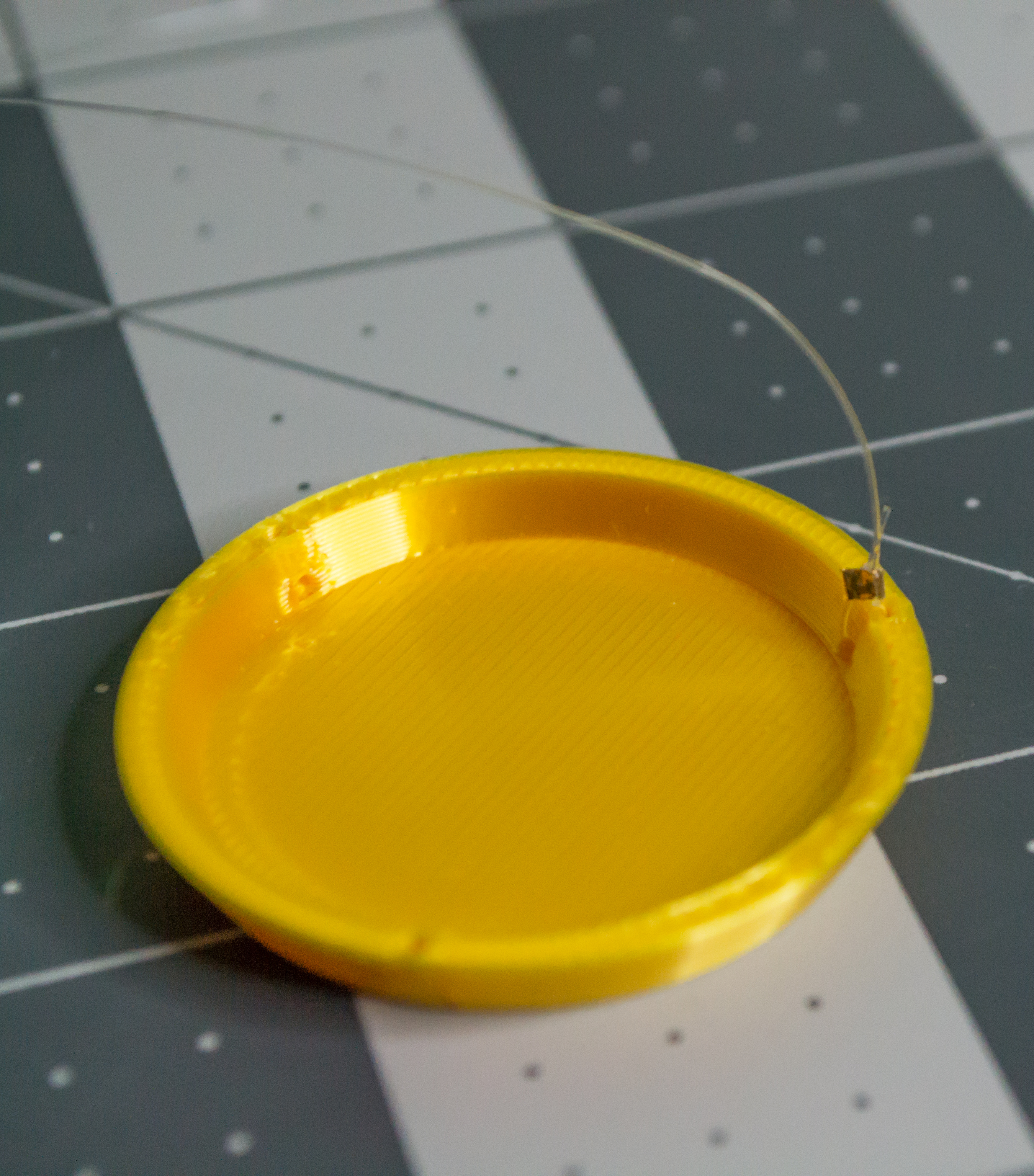
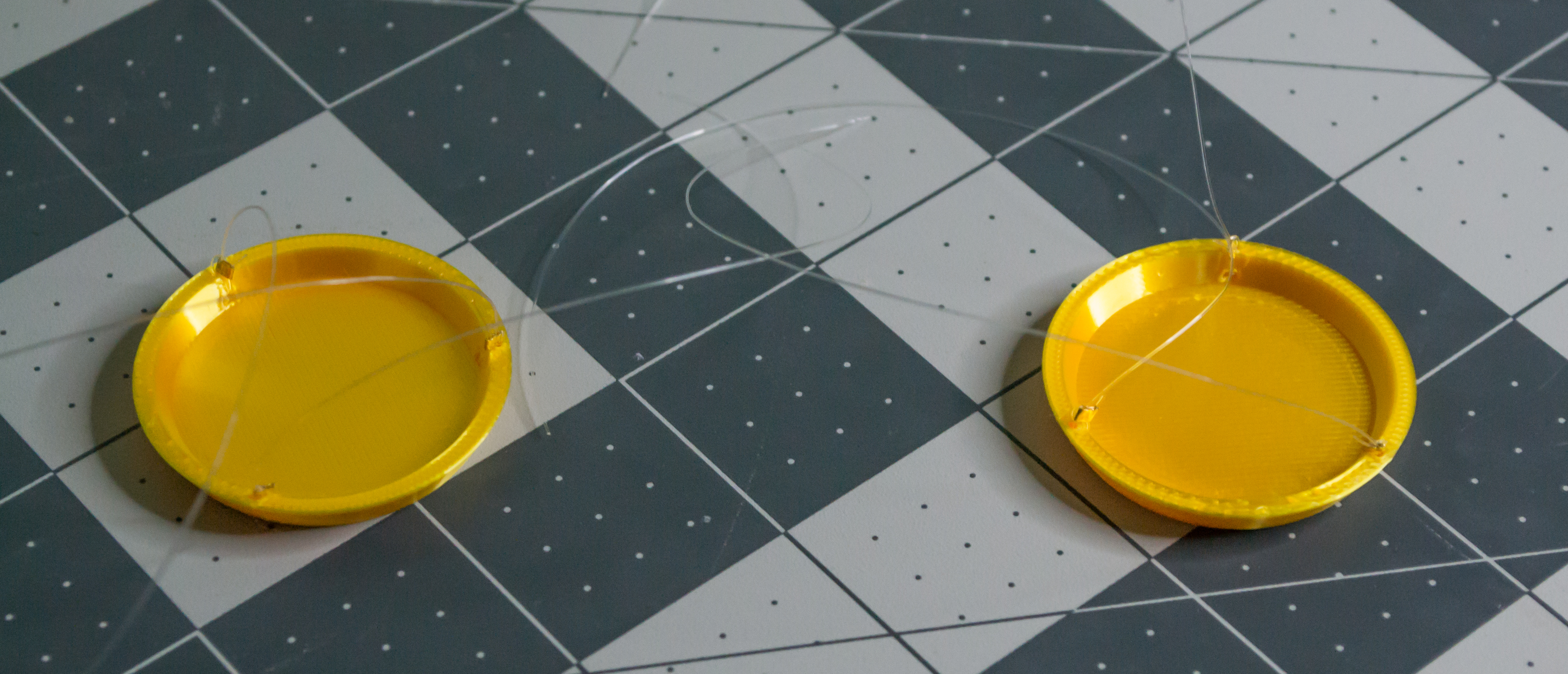
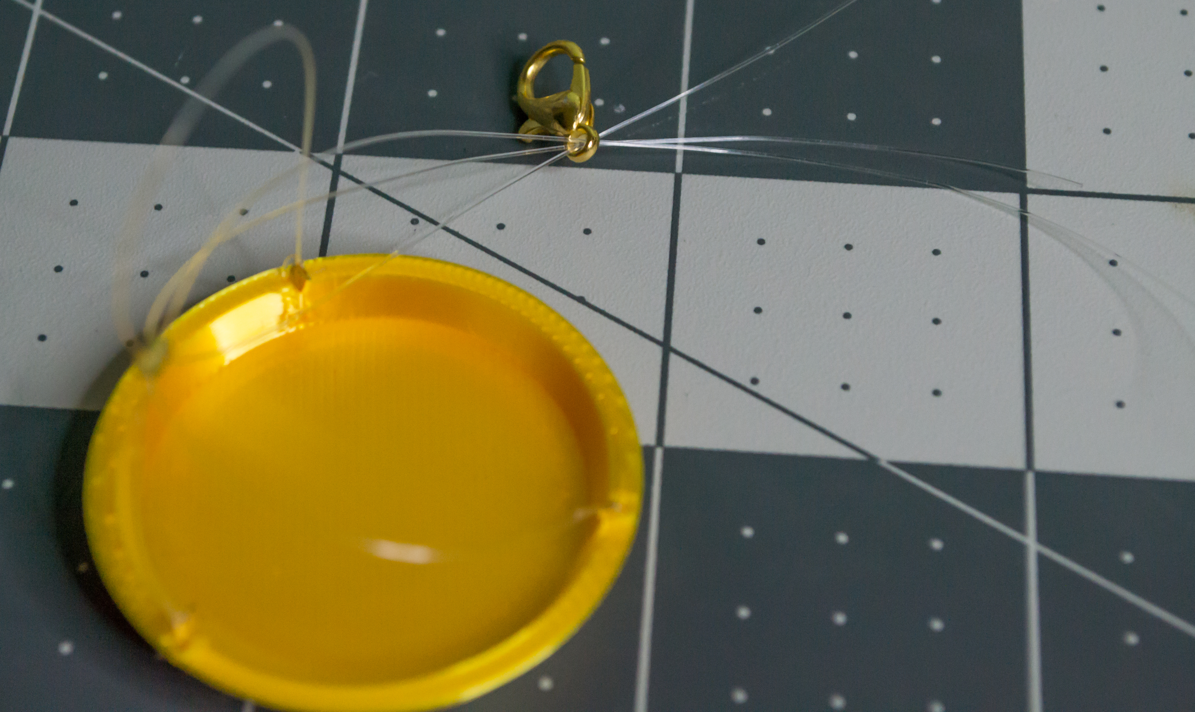
Repeat that process five more times so each of the two Plates has three monofilament lines attached. The result should look like this.
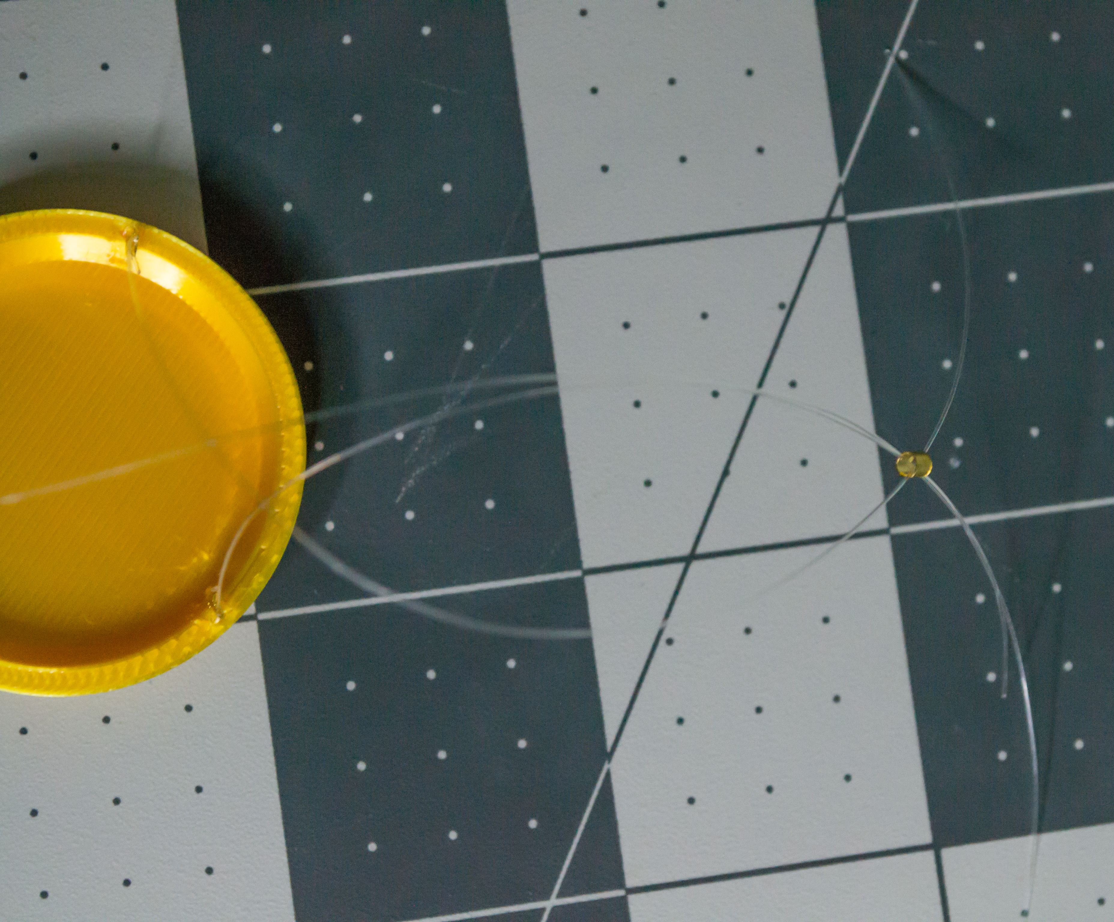
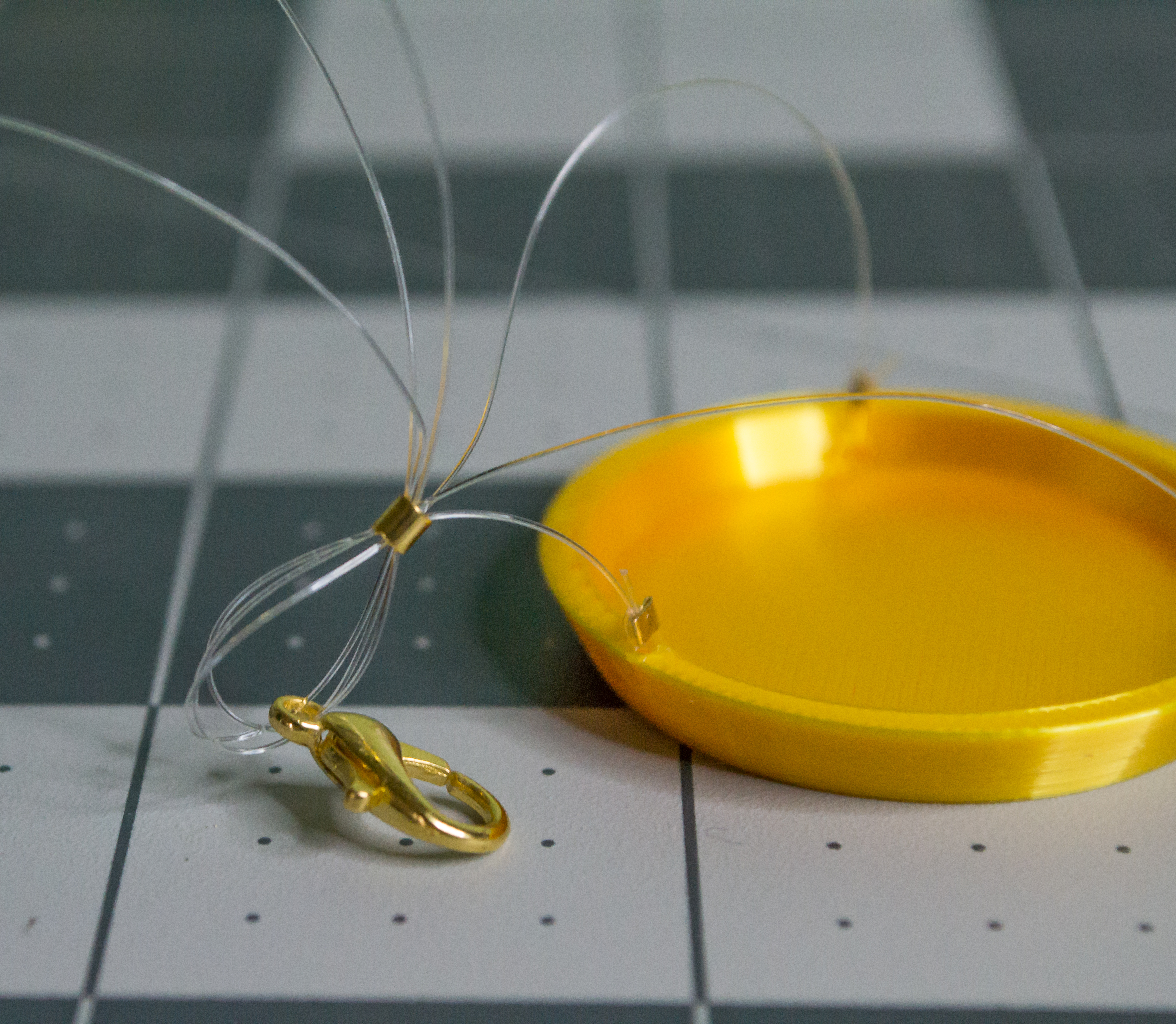
For each Plate, take one medium gold crimp bead and push all three monofilament lines through it. Then add one gold lobster claw clasp after the medium crimp bead.
 ➜
➜
 ➜
➜
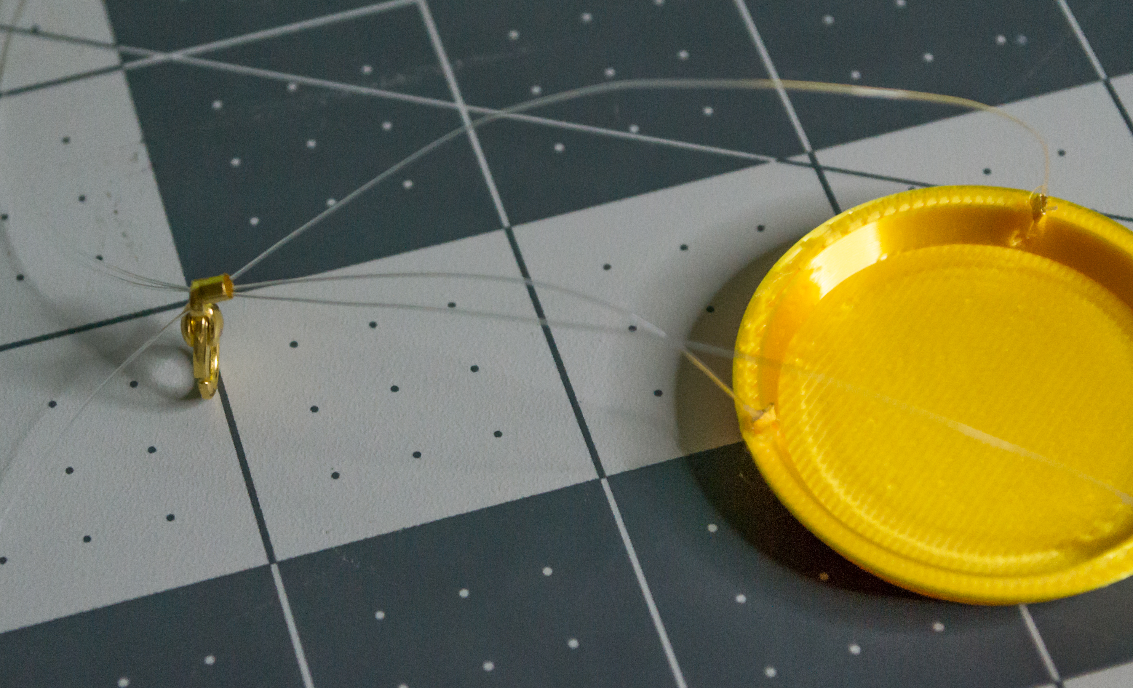
Now, loop the three lines back around and into the medium gold crimp bead.
Wrap the three monofilament lines around again to make a locking loop. This helps keep the plate hanger from sliding.
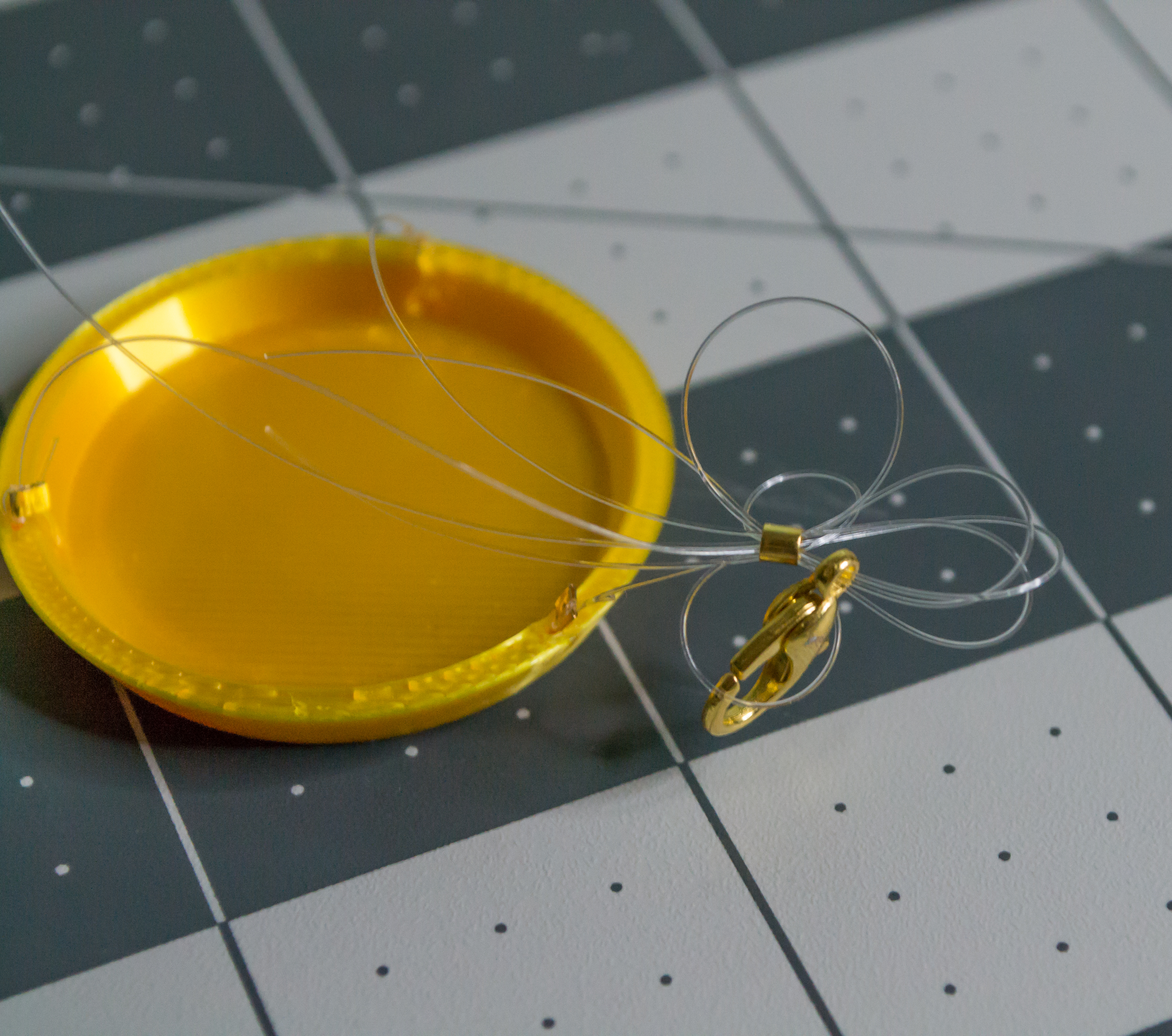
At this point, I recommend setting up the other Plate as well so you can compare their hanging heights before crimping. Once both heights look even, move each medium crimp bead as close as possible to its lobster claw clasp and crimp it.
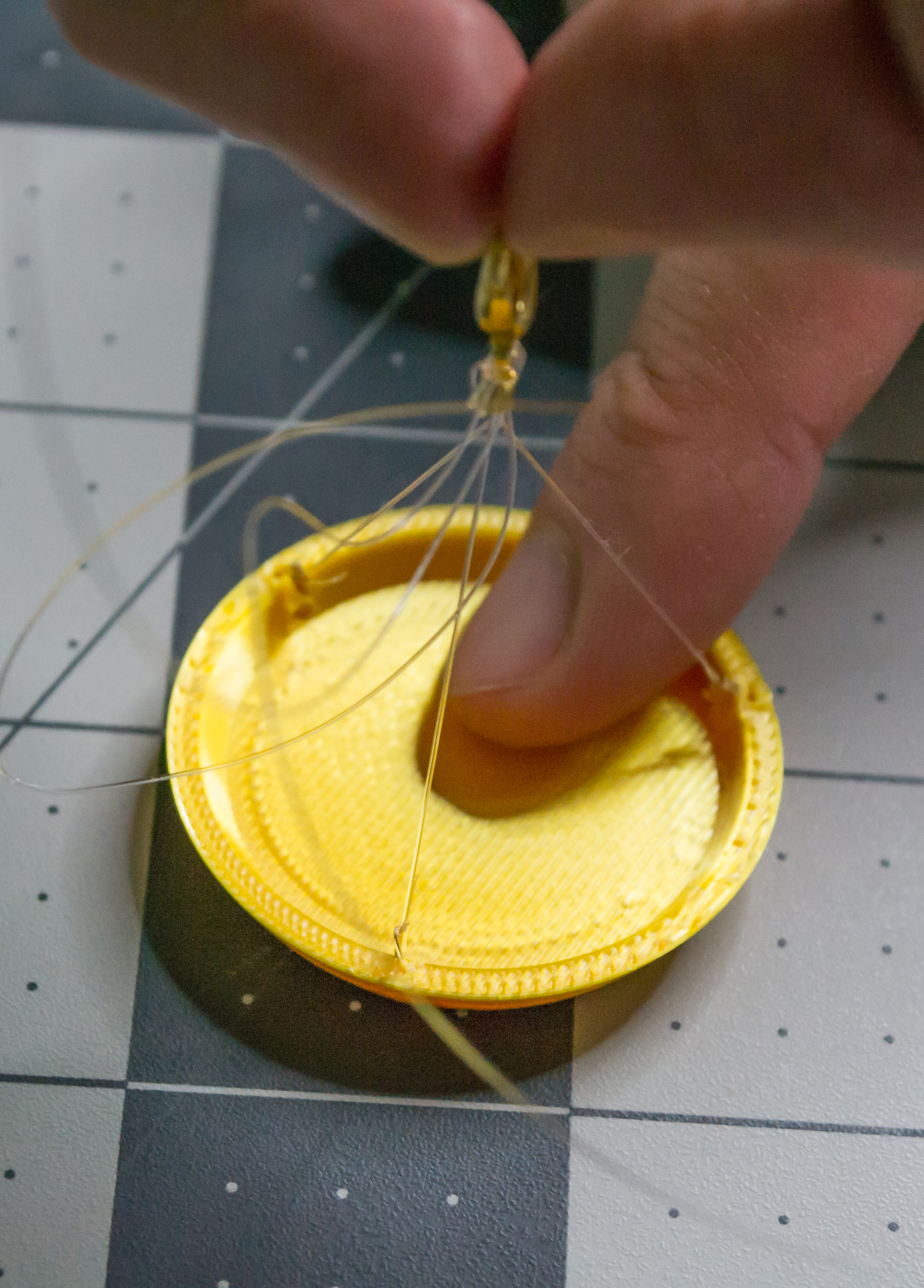 ➜
➜
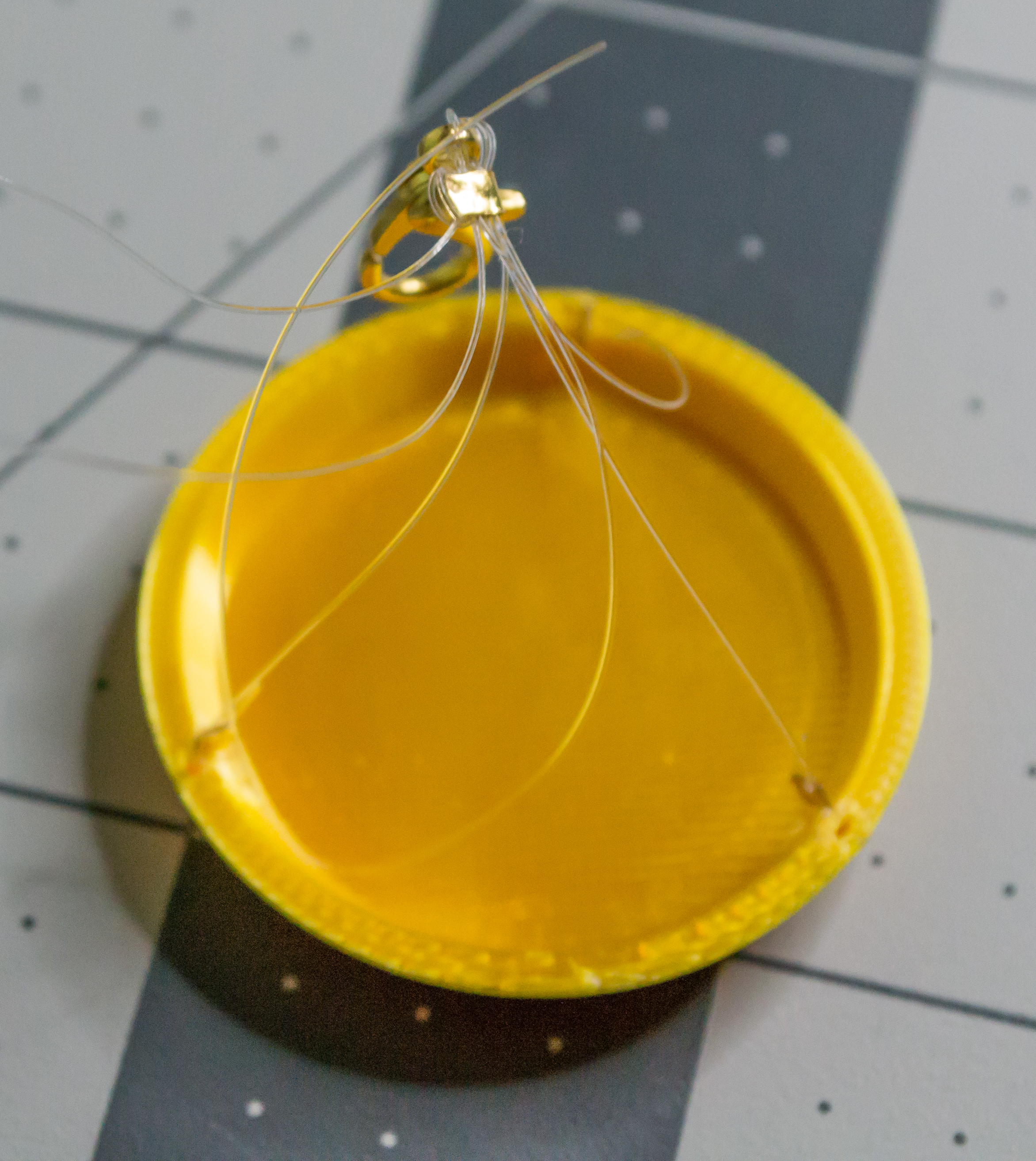 ➜
➜
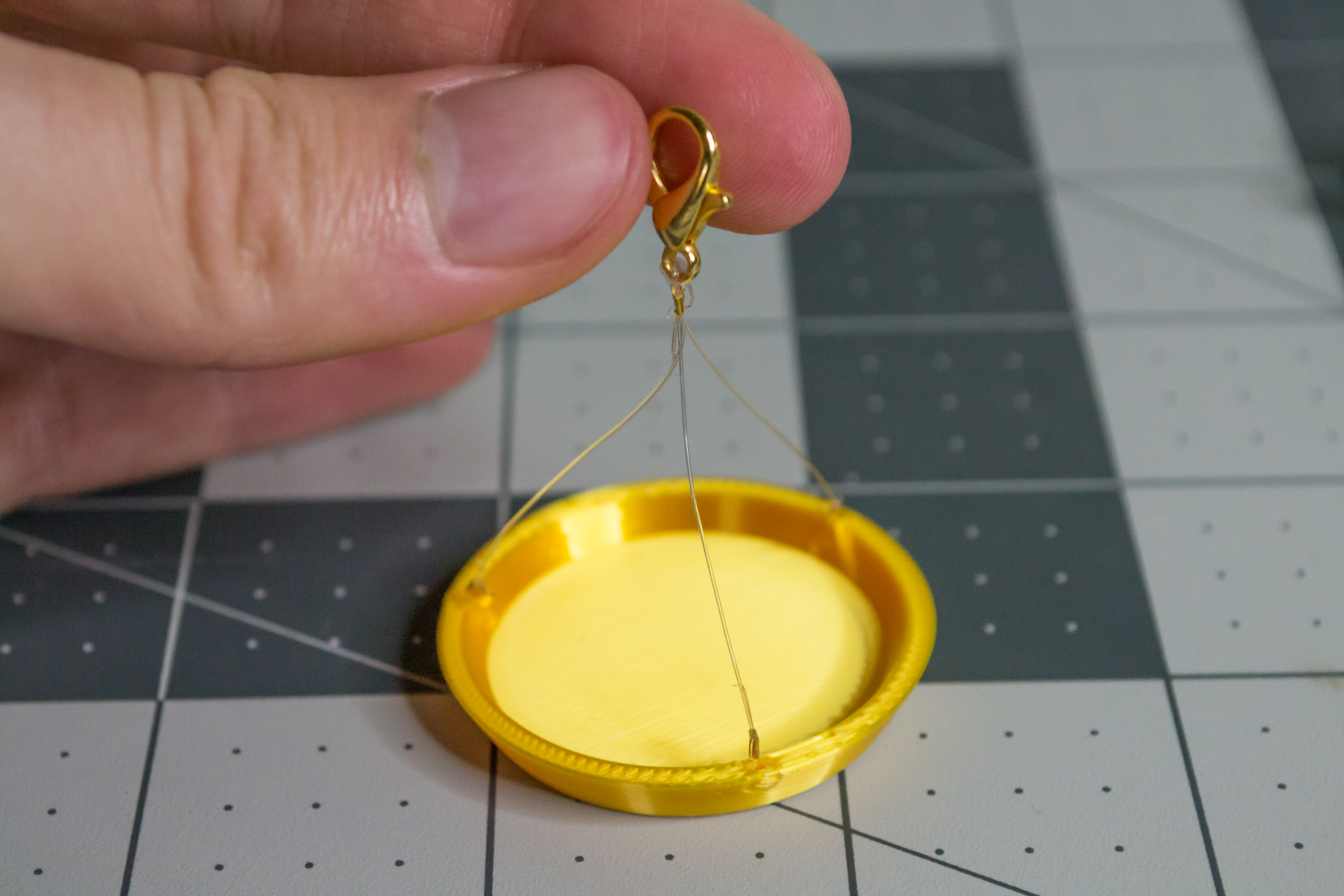
The final result of both plates should look like this.
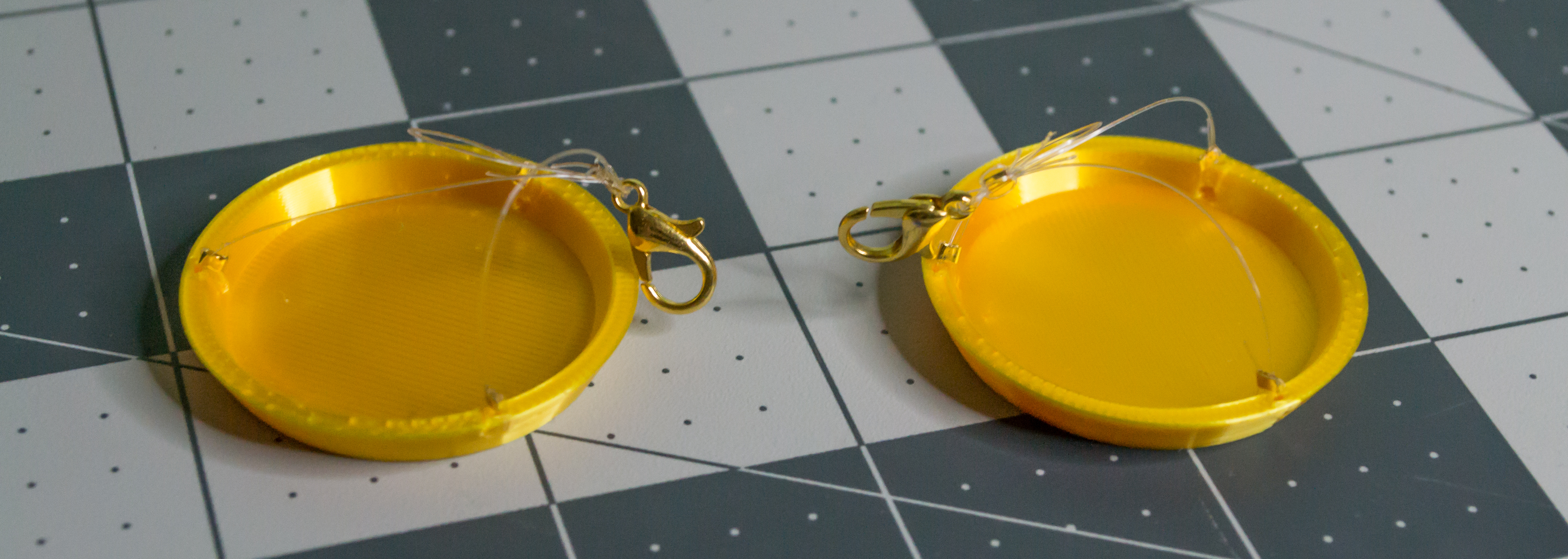
Check: Both hanging Plates should have three clear monofilament lines, one medium gold crimp bead, and one gold lobster claw clasp. Compare the two plate heights before crimping the medium gold crimp beads.
Now attach both Plates to the holes at the ends of the Lever.
The final assembly step is to use the last M2, 8 mm machine screw to secure the back.
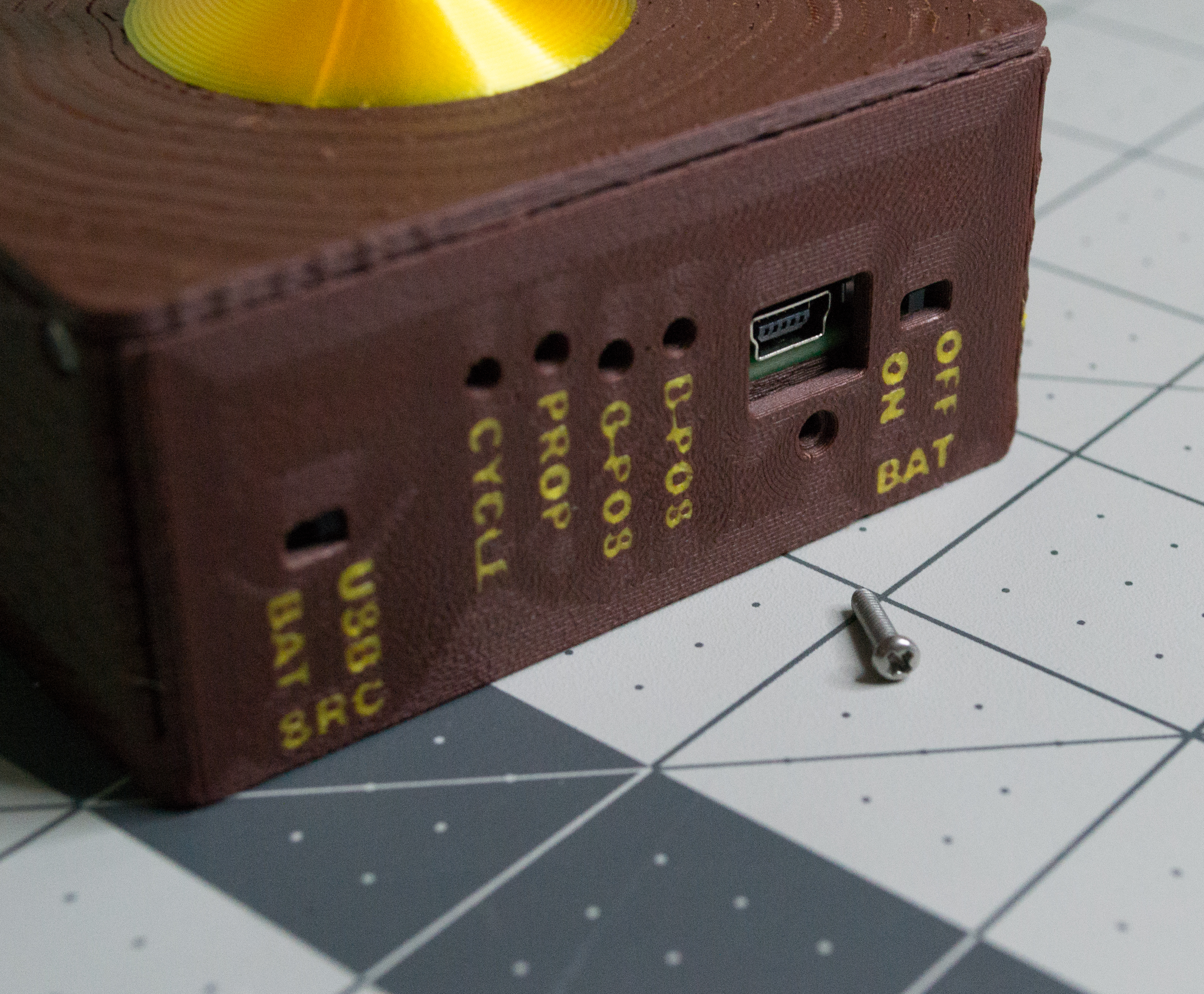 ➜
➜
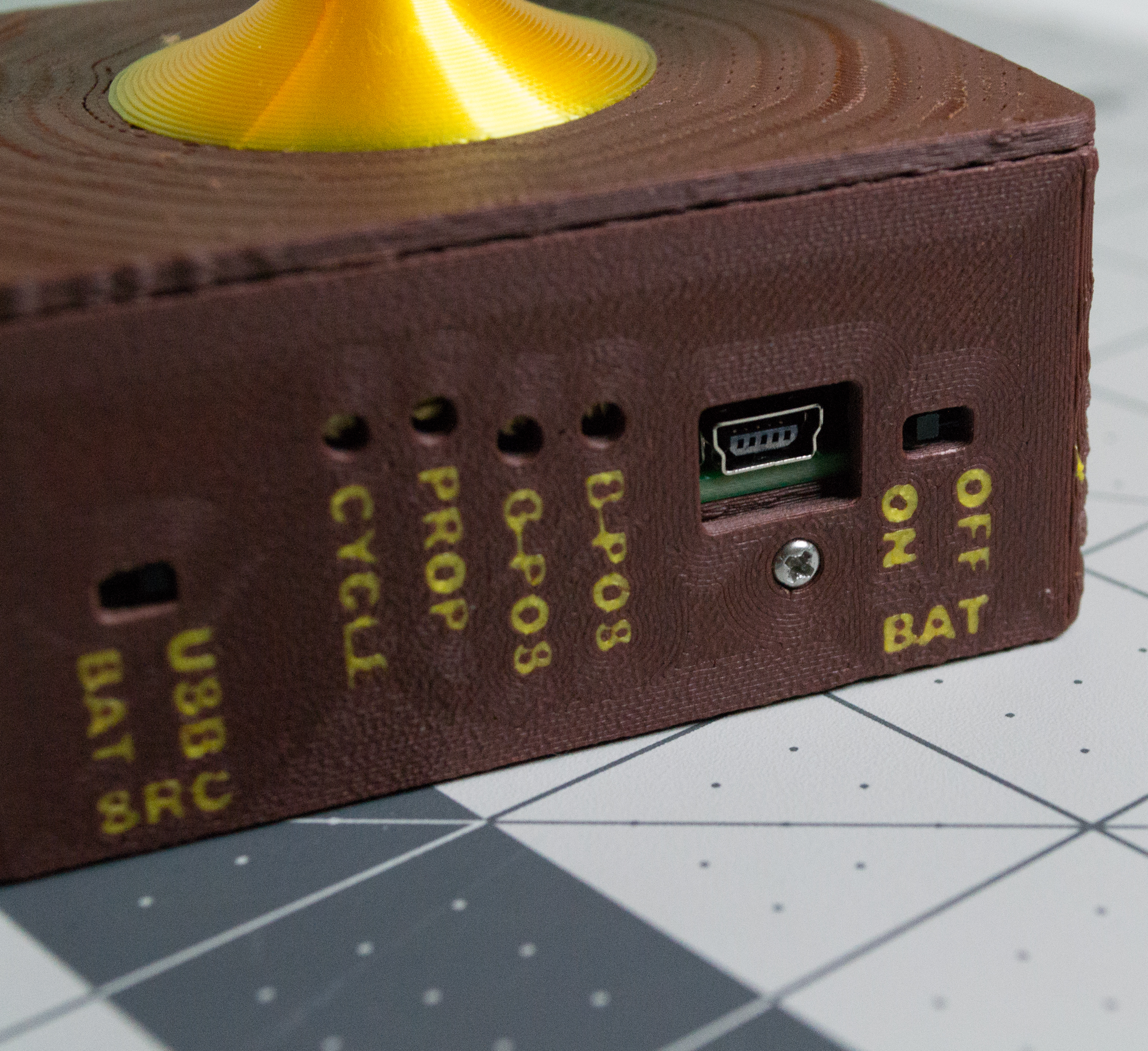
Check: The final M2, 8 mm machine screw should secure the back without forcing the plastic, and both Plates should hang freely from the Lever.
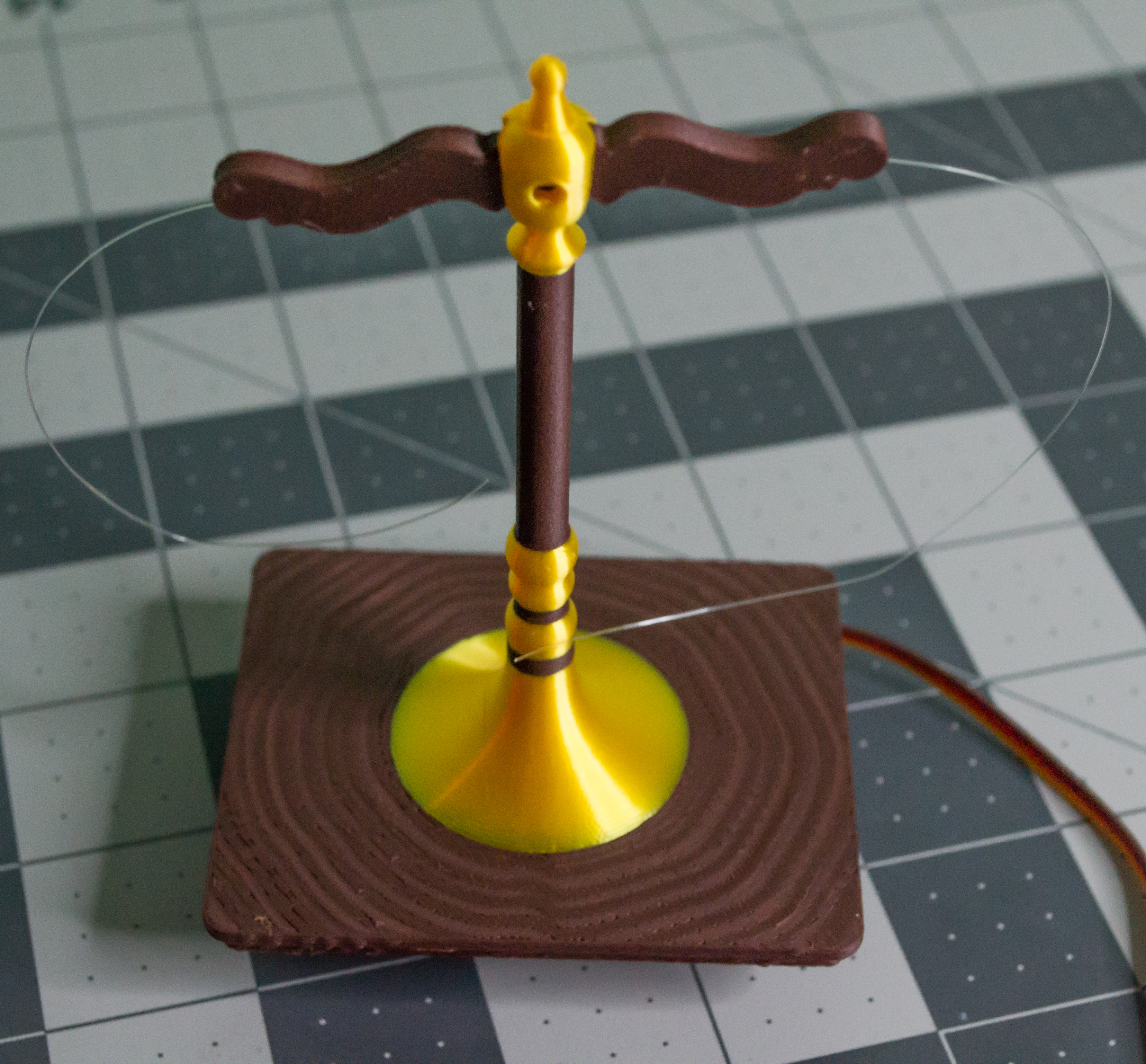
VintageScale is now assembled. Power it from USB Mini-B or three 1.2 V AAA rechargeable batteries, choose a few objects or ideas to compare, and place it somewhere it can be seen.
Trinkets and Meaning
Overview
To make VintageScale your own, add something meaningful to the two Plates. I have provided basic 3D models for pieces that say Work and Life, which you can print and place on the scale. However, I highly encourage you to make your own pieces instead.
VintageScale does not have to measure real weight. The two sides can represent ideas, priorities, choices, memories, or small objects. That is where the project becomes more personal.
Models
| File | Link |
| - | - |
| VintageScale.work | https://a360.co/4yiWC7U |
| VintageScale.life | https://a360.co/4eSNGyt |
Making Your Own
A few ways to attach your own items are:
- Glue the item to the Plate.
- Make a small weighted base.
- Add magnets.
- Add hook-and-loop tape, such as Velcro.
Before getting into the small details, it helps to first choose an idea that you actually contemplate. The two sides do not need to be opposites, and they do not need to be serious. They just need to mean something to you or to the person receiving the project.
For example, you could make the scale about Work and Life, but you could also make it about Logic and Creativity, Past and Future, Save and Spend, or two small objects that remind you of a decision or memory. The best version is one where the two sides make someone stop for a second and think.
When designing your own trinkets, try to keep them small and light. VintageScale is a decorative display, not a real measuring scale, so heavy objects can make the Plates hang unevenly or put extra load on the servo linkage. If you want to use a heavier object, consider making a lightweight printed version of it.
The most important part is that the objects should feel intentional. A simple pair of words, symbols, or small printed shapes can make the whole project feel much more personal.
Calibration and Operation
Overview
This section explains how to adjust the TwoPositionServo controller board after VintageScale is assembled.
Quick Reference
Controller Adjustments
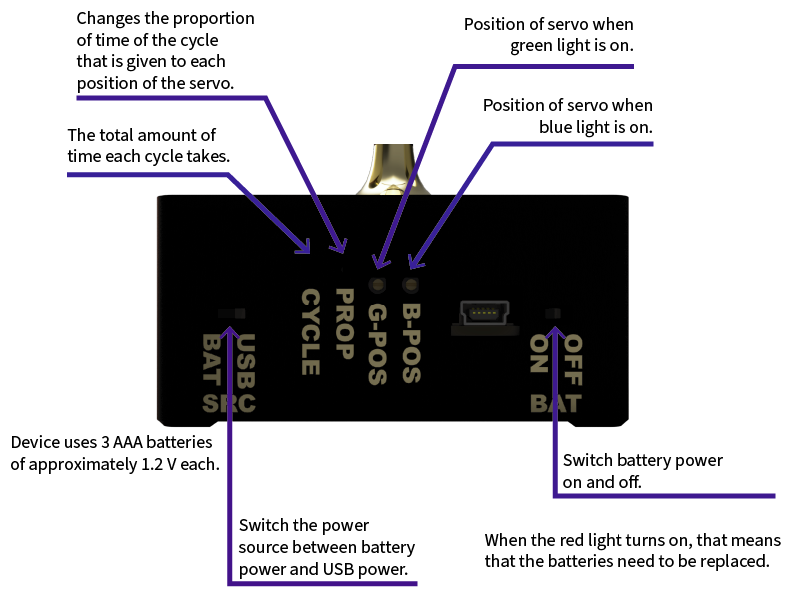
Use a small flat-blade screwdriver to adjust the onboard potentiometers. There are four potentiometers that control the timing and servo positions.
The leftmost potentiometer is Cycle. It sets how long one full cycle takes. One cycle is the time it takes for both servo positions to be reached before the sequence restarts. Turning it left reduces the cycle time; turning it right increases the cycle time.
The second potentiometer from the left is Proportion. It controls how much of the total cycle time is spent at each servo position.
The last two potentiometers set the two servo positions. Adjust these slowly so the mechanism does not bind.
There are also two switches: one for selecting the power source and one for battery power.
The left switch is Source, which selects USB or battery power. The right switch is Battery, which turns battery power on or off. If you are using batteries, set Source to BAT and set Battery to ON.